Analyzing UART Messages on Wokwi Logic Analyzer Part 2
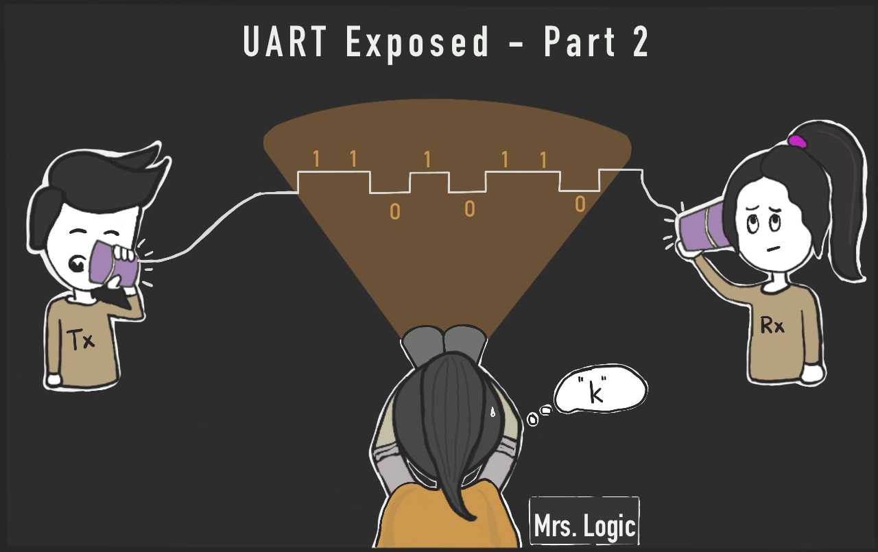
What's baud rate, parity, start and stop bits? Join us for a journey diving deep into UART internals

The Wokwi Logic Analyzer is a virtual instrument that helps us analyze and debug digital signals. We discussed its basic operation and how to connect it to your development board (e.g., Arduino Uno) in the previous article.
In this article, we’ll dive into how UART works by setting different configuration options and analyzing the result in the Logic Analyzer. We will:
- Change the baud rate and monitor the timings of the UART transmit signal pin;
- Vary the number of stop bits and observe the changes in the signal; and
- Enable and disable parity bits and see how they are reflected in the Tx signal.
Let's Analyze! 🕵🏽♂️
Baud Rate: Not What You Expect
In the first part, we printed a text message using this project Logic Analyzer Demonstration playground. We'll keep using the same playground for this blog post.
The Baud Rate
When we configure UART (e.g., using Serial.begin()), we specify the baud rate. The baud rate defines how many bits we send every second.
This also implies that the time it takes to transmit a single bit is the inverse of the baud rate. For example, if the width of a single bit is 104 µs (or 0.000104 seconds), then the UART baud rate is 1/.000104 or 9600.
The baud rate calculation comes in handy when we want to find the baud rate by looking at the signal. Let’s measure the bit width of the UART message in our playground project:️

In the screenshot above, the UART signal alternates between digital high and low. We highlighted two points of interest:
- The cursor option is used to measure the time duration between two points
- The UART signal data
Next, we'll zoom in on the waveform and measure the baud rate using the cursor.
Measuring The Baud Rate
The playground project sets the baud rate to 115,200 by calling Serial.begin(115200) at the beginning of the setup() function.
We'll measure the time it takes to transmit a single bit by looking at the signal and searching for the smallest interval where the signal goes high. We want to find the smallest interval, since there can be a group of several consecutive 1 bits, and we want to find the time it takes to transmit just a single bit.
Zoom in, press Shift, then click and drag from the point the signal goes high to the point it goes low to select this region:

The logic analyzer shows that interval we marked — the time it takes to transmit a single bit — is 8.5 µs, and the signal frequency is 117.647 kHz . Meaning, the actual baud rate is 117,647.
How come we didn't get 115,200, as we defined in the code?
There are several factors that can contribute to this deviation - about the 2% difference between the baud rate we defined and the baud rate we measured:
- The device's clock speed Arduino Uno has a clock rate of
16 MHz, or 16 million ticks per second. Unfortunately,16,000,000does not divide by115,200. So the Arduino can only generate a baud rate that is close to the value we asked for and not the accurate value. - Logic Analyzers have a limited sampling rate. In Wokwi, you get
1 GHz, which is more than enough for accurately recording 115,200 baud rate, but a real-life logic analyzer will probably have a slower baud rate.
Even when using Wokwi, the "Downsampling factor" setting in PulseView reduces the actual sampling rate. - When working with physical hardware, the clock rate will be affected by environmental factors such as temperature. These effects are usually minor, but they can still cause variations that you can observe in your measurements.
Luckily, the tolerance of the receiving devices is usually within the 5% range, so we don't have to worry about minor deviations.
Going Slower
Now, we’ll set the signal’s baud rate to 9600 and then measure the actual signal baud rate on the Arduino Tx Pin:
Serial.begin(9600);
After running the simulation again, we can download the VCD file, open it in PulseView and see the signal.
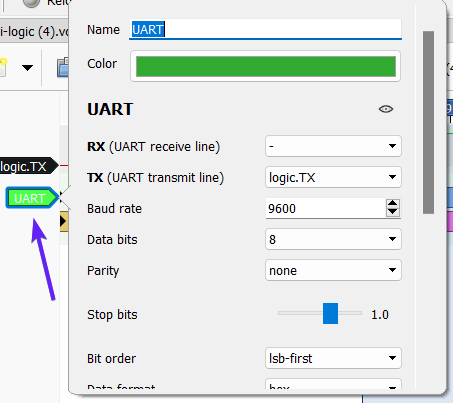
If you are using the UART Protocol Analyzer in PulseView (as we did in the first part of this blog series), don't forget to update the baud rate setting there:

And now... let's measure! 📏

The measured baud rate is now 9,615 bps. This shows a deviation of less than 0.2%.
Baud Rate Deviations
By looking at UART signal with the logic analyzer, we were able to find the actual baud rate of the signal.
You can also find the expected deviation for each baud rate setting in the datasheet of your microcontroller. For the Arduino Uno, that is the ATmega328p datasheet.
The following table shows the deviations when running at 16MHz:

Serial signal. Start and Stop Bits
After looking at individual bits, let's talk about how UART transmit bytes of data.
When the line is idle, and there is no data to transmit, the signal is high. Then, when the transmitter wants to transmit a byte of data, it sends the following sequence bits (when using the standard Serial settings):
- Start bit - always
0 - Eight bits with the actual data
- Stop bit - always
1
You can observe these in the screen shot below. PulseView marks the start bits (which are always low) with S, and the stop bits with T:

You can also see the eight bits of data that make each byte, and the idle signal at the beginning - it stays high until the first start bit.
But this is just the standard UART - let's take a look at how we can make it a bit more interesting...
Non-Standard Serial Settings
Let's zoom in around the stop bit:

As we explained above, the signal goes high during the stop bit (the stop bit is always logical 1). However, the signal is also high when transmission is idle.
This means that the signal can stay high for longer than a single bit time. In fact, it'll stay high until a new byte is ready for transmission. The stop bit must be at least as wide as the other bits (as dictated by the baud rate), but it can stretch longer.
However, we can force the stop bit to be even longer, increasing the idle time between bytes.
Serial.Begin's Secret Parameter
Did you know that Serial.begin() also accepts a second, optional parameter following the baud rate?
Most Arduino developers don't know it, but you can specify a non standard UART configuration using the second parameter of Serial.begin(). The following table summarizes the supported configurations:
| Value | Data bits | Stop bits | Parity |
|---|---|---|---|
SERIAL_5N1 |
5 | 1 | None |
SERIAL_6N1 |
6 | 1 | None |
SERIAL_7N1 |
7 | 1 | None |
SERIAL_8N1 * |
8 | 1 | None |
SERIAL_5N2 |
5 | 2 | None |
SERIAL_6N2 |
6 | 2 | None |
SERIAL_7N2 |
7 | 2 | None |
SERIAL_8N2 |
8 | 2 | None |
SERIAL_5E1 |
5 | 1 | Even |
SERIAL_6E1 |
6 | 1 | Even |
SERIAL_7E1 |
7 | 1 | Even |
SERIAL_8E1 |
8 | 1 | Even |
SERIAL_5E2 |
5 | 2 | Even |
SERIAL_6E2 |
6 | 2 | Even |
SERIAL_7E2 |
7 | 2 | Even |
SERIAL_8E2 |
8 | 2 | Even |
SERIAL_5O1 |
5 | 1 | Odd |
SERIAL_6O1 |
6 | 1 | Odd |
SERIAL_7O1 |
7 | 1 | Odd |
SERIAL_8O1 |
8 | 1 | Odd |
SERIAL_5O2 |
5 | 2 | Odd |
SERIAL_6O2 |
6 | 2 | Odd |
SERIAL_7O2 |
7 | 2 | Odd |
SERIAL_8O2 |
8 | 2 | Odd |
* This is the default value
You may notice the pattern here: The first number after SERIAL_ determines the number of data bits (5, 6, 7, or 8), the next letter determines the parity: N means No parity, E means Even parity, and O means Odd parity. The final number determines the number of stop bits (1 or 2).
We'll talk about the data bits and parity later. For now, let's see what happens if we change the serial configuration to have two stop bits instead of one.
Two Are Better Than One?
Let's see what happens if we change the UART configuration to transmit two stop bits instead of one. The default configuration is SERIAL_8N1, so we'll go with a similar configuration, changing only the number of stop bits from 1 to 2.
This gives SERIAL_8N2. Change the first line in setup() to read:
Serial.begin(9600, SERIAL_8N2);Run the simulation, stop it after a few second and load the logic analyzer VCD file into PulseView software. You'll see that there are now two stop bits instead of one (the high time of the signal is twice the length of each data bit):

The stop bit’s width is now twice that of a single bit. Neat, isn't it?
Parity Bit
Parity bit is a simple error detection mechanism — it allow the receiver to find errors in the transmitted data. The parity bit, if present, is sent right after the data bits, and before the stop bit(s).
The term "parity" refers to the number of high (1) bits in each transmitted byte (including the data bits and the parity bit). We say that the parity is even if there is an even number of high bits, and odd if there is an odd number of parity bits.
There are three possible configurations for the parity bit:
- No parity - the default. This is what we've seen so far.
- Even parity - all the bytes must have even parity. The parity bit is set to
0if the data bits have an even number of ones. The parity bit is set to1if the data bits have an odd number of ones. - Odd parity - the opposite of even parity. The parity bit is set to
0if the data bits have an odd number of ones. The parity bit is set to1if the data bits have an even number of ones.
Consider the data you are sending. If you see that most of the data are inclined towards even parity frame then select even parity. Else odd.
or, Toss a coin!
Here's an example that illustrates what the parity bits may look like given different values of the data bits, in both even and odd parity configurations:
| Original data | Even parity | Odd parity |
|---|---|---|
0 0 0 0 0 0 0 0 |
0 |
1 |
0 1 0 1 1 0 1 1 |
1 |
0 |
0 1 0 1 0 1 0 1 |
1 |
0 |
1 1 1 1 1 1 1 1 |
0 |
1 |
1 0 0 0 0 0 0 0 |
1 |
0 |
0 1 0 0 1 0 0 1 |
1 |
0 |
Playing Parity
We'll configure UART to use an even parity bit by changing the call to Serial.begin() as follows:
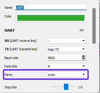
Serial.begin(9600, SERIAL_8E1);Then, run the simulation and load the VCD file into PulseView. This time, when you configure the UART protocol analyzer, make sure to set the Parity option to even:

The first transmitted character is ‘W’. The data bits have total of five ones. The parity bit is high, in order to make even number of ones:

The next transmitted character is ‘e’. It has four logic ones. The parity bit is low, in order to keep the total number of logic ones even:

Odd Parity
Similarly, we can configure Serial to use odd parity:
Serial.begin(9600, SERIAL_8O1);Looking at the signal PulseView (remember to configure the UART Protocol Analyzer with odd parity), we can see that now the number of ones in the first transmitted character is five, and the parity bit is 0, to keep the number of ones odd:

The next character is ‘e’. It has four logic ones, so the parity is now high to make the total number of ones odd. Exactly the opposite of what we had before:

The answer is both yes and no. If the device or machine you're working with requires it, then you have to use it. There's no getting around it 👻
But here's the thing, the parity bit is important for catching mistakes that can happen when sending data, like if there's noise or the clock on one device is somewhat inaccurate. So, in short, even though it might not always be required, it's still a good idea to use it because it helps keep your data accurate.
Data Bits
Nowadays, bytes are always made of 8 bits. In the past, however, the size of a byte varied between systems. Arduino's UART implementation supports such legacy systems - you can choose between 5, 6, 7 or 8 data bits per byte. Other microcontrollers, such as the STM32, even support 9 data bits.
We invite you to experiment with different data bits settings (e.g. SERIAL_7N1 for 7 bits), and observe the UART signal with the logic analyzer. You already know how to use it like a pro!
Conclusion
UART is a relatively simple protocol, and now you know then ins-and-outs of it, including some of the more esoteric features, such as parity bits and non-standard number of data bits.
More importantly, you've gained a new skill — you learned how to use the logic analyzers to dive into the internals of digital communication protocols and study how they work. You can also use this skill to debug communication issues.
We're planning more articles in this series, covering additional protocols, such as SPI, I2C, Neopixels, and looking into signals such as PWM and servo motor control.
If you have any feedback or suggestions to make the simulator more helpful, you can always connect with us on Discord, Facebook, and Twitter.

