Learn to Control Servo motor using PWM - Wokwi Style
Experiment with PWM and servo angle to understand the relationship and explore other aspects of Servo motor control in a hands-on approach.

Introduction
The Servo motor is a versatile device used for motion control in electromechanical projects. You can use it in various fields, including robotics, medical devices, and security.
The Servo motor uses only one IO pin to control the position. You can understand the basics of servo motor control by monitoring it using the Wokwi logic analyzer. The logic analyzer is a simulated instrument that shows the voltage status on the pins, measures pulse widths, observes timings between two events, and more!
Let's get started!
Basics of a Servo Motor
How does a Servo motor work?
A servo motor is an electromechanical device. It has an electronic board that accepts PWM (Pulse Width Modulation) signals and measures its on-time pulse width. The servo motor also has a potentiometer that helps in keeping track of the shaft position.
The embedded board continuously detects and corrects the unintended shift in the shaft position. The target position is maintained by continuous error correction between the shaft position and the user input.
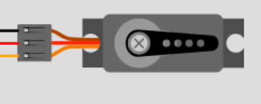
In the image below, you see a very common hobby servo motor. It has three pins:
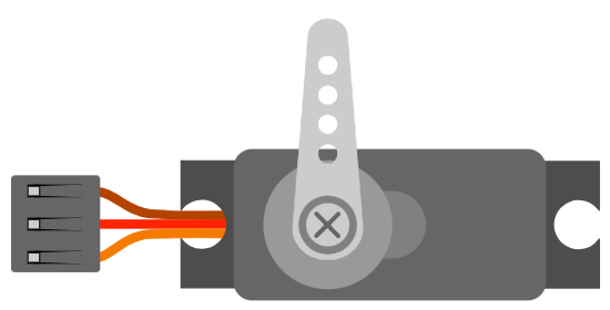
| Name | Wire Color | Description |
|---|---|---|
| PWM | Yellow | Input control signal for the motor |
| V+ | Red | Positive supply terminal |
| Ground | Brown | Ground terminal |
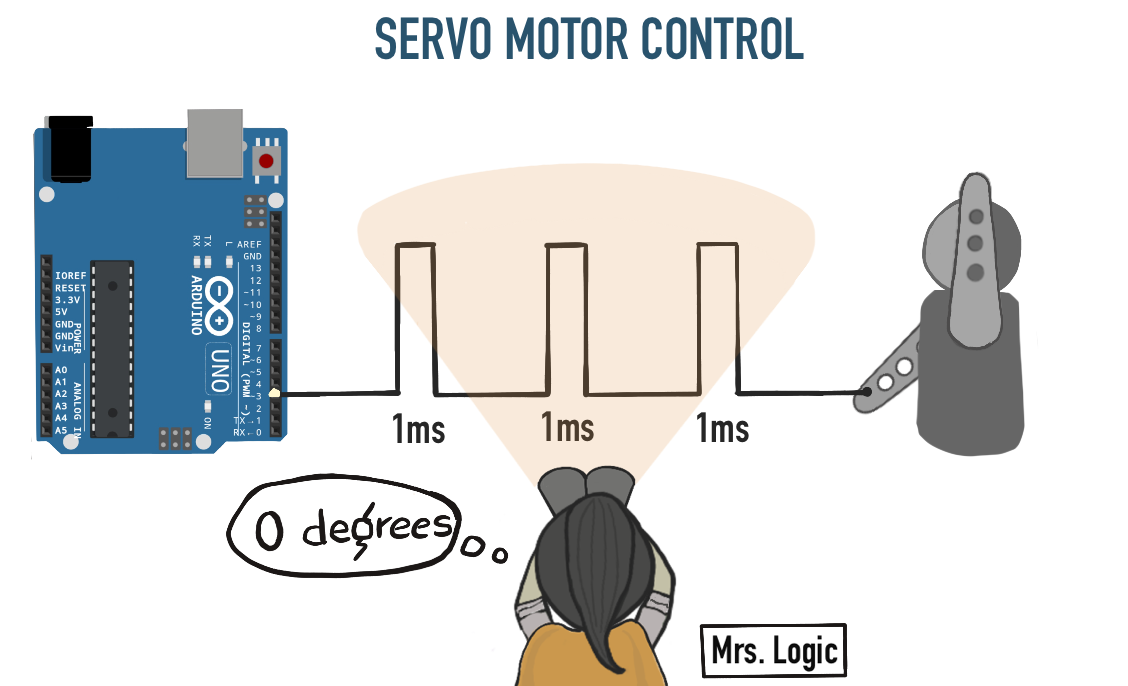
To control the servo motor, you send a PWM signal with a frequency of 50 Hz. The usual frequency can be between 40 Hz and 400 Hz.
40 Hz over 400 Hz? (or viceversa)As you increase the frequency of the PWM signal, the time given for the servo to reach new posistion reduces.
400 Hz implies a latency of 2.5 ms versus 25 ms latency ( 40 Hz ). It's a tradeoff between better precision( 40 Hz ) and faster operation( 400 Hz ).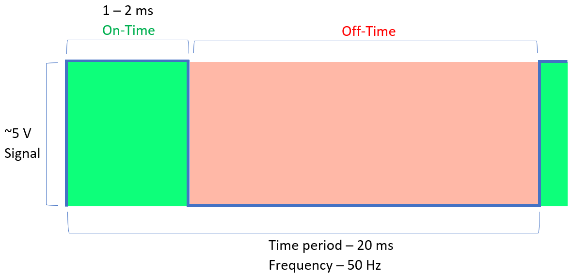
You can rotate the servo motor shaft from 0° to 180° by varying the PWM pulse width from 1 ms to 2 ms.
Here’s a cheat sheet for the shaft’s position in a typical hobby servo motor:
- "
0°" (~1 mspulse) - "
90°” (~1.5 mspulse) - "
180°" (~2 mspulse)
Continuous servo motors are a type of servo motor that can rotate a full 360 degrees continuously in either direction rather than moving to only specific positions. In this case, you can control the direction but not the position using PWM.
Monitoring the Servo motor signal on the Wokwi logic analyzer
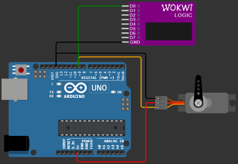
You can start faster with a pre-built Servo motor project. The control signal of the servo motor is connected to Pin 9 of the Arduino and D0 of the logic analyzer. The brown wire goes to ground, while the red wire is connected to Arduino’s 5 V source.
Let’s drive the stepper motor to 0°, 90°, and 180° and observe the waveform on the Servo control signal pin.
Case 1: Servo at 0° position
Copy and paste the below code into the editor window of the prebuilt project above.
#include <Servo.h>

Servo myservo;  // create servo object to control a servo

int pos = 0;    // variable to store the servo position

void setup() {
  myservo.attach(9);  // attaches the servo on pin 9 to the servo object
}

void loop() {
  myservo.write(0);
}
The line below sets the servo motor's shaft position.
myservo.write(0);
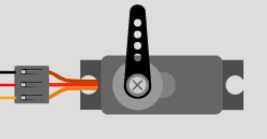
Run the simulation and observe the servo motor’s shaft position. It’s now in the extreme left position, as shown in the image below.
Observing the pulse width of the PWM signal using the logic analyzer data shows that the ON width is about 0.5 ms.
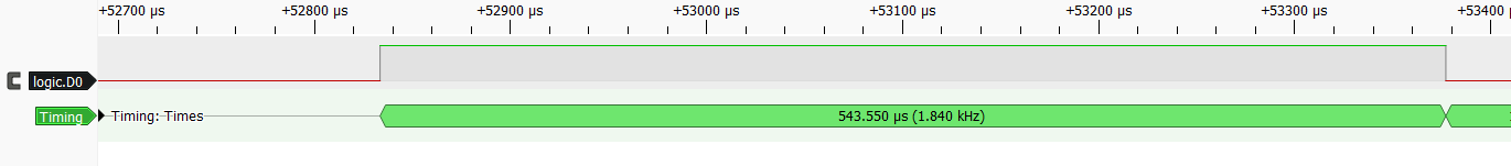
The frequency is about 50 Hz.
Did you notice that the servo motor angle only depends on the
ON time of the signal? Even if you change the frequency from 50 Hz to 100 Hz, the servo motor angle will remain the same. Hence servo motor is not a true PWM controlled device.PWM conveys the information on the power delivered which doesnt reflect in the servo motor position.
take an example - A PWM signal with
2 ms on time and 2.5 ms period ( 80% dutycycle), delivers more power than a PWM signal with 2 ms on time and a 50 ms period ( 5% duty cycle). The servo would resond in the same way for both PWM signals.
Case 2: Servo at 90° position
Update the parameter you send in the myservo.write function to turn the servo motor by 90°.
myservo.write(90);Rerun the simulation and look at the servo motor position. It’s now in the center position.
Let’s now observe the pulse width of the PWM signal using the logic analyzer data that corresponds to the center position of the motor.
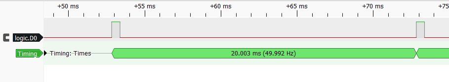
The ON width is about 1.5 ms.
The frequency is still 50 Hz (20 ms). The frequency never change. Only the PWM on time pulse width changes.
Case 3: Servo at 180° position
Update the parameter you send in the myservo.write function to turn the servo motor by 180°.
myservo.write(180);
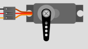
Rerun the simulation and look at the servo motor position. It has now moved to the extreme right position.
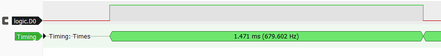
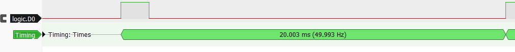
Now, please look at the PWM signal's pulse width using the logic analyzer data that corresponds to the extreme right position of the motor shaft.
The ON width is 2.4 ms.
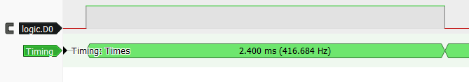
The frequency is still 50 Hz (20 ms). No change in the frequency.

The pulse width expected was
2 ms for a rotation of 180°, but we measured 2.4 ms here. The actual pulse widths vary by type and make of servo motor. You may even notice the differences in the same batch of servo motors. Depending on the precision you need, you may have to calibrate the servo motor first, one time.
Bonus section - Servo motor with feedback
A servo motor includes feedback circuitry that helps the motor to continuously adjust the shaft position. Specific servo motors also feature an additional fourth line that outputs an analog value indicating the current shaft position.
The servo motor controls the position of the shaft based on the PWM pulse width, but why should I still read the feedback if the servo control circuitry already takes care of position precision?
The additional feedback signal is useful in many situations.
Insufficient power - Insufficient power to drive the load can cause the servo motor to stop at a position other than the intended one.
Why would this happen? This can occur if the power supply to the motor is not strong enough to overcome the resistance of the load, causing the motor to stall or stop before reaching the desired position.
Other factors that can cause this issue include improper voltage⚡ or current settings, mechanical issues with the motor or load, and electronic problems with the control circuit.
Wiring issue - One potential issue that could cause the servo motor to stop at the wrong position due to insufficient power is a disconnected control wire. This can be difficult to detect in a three-wire servo as there is no direct way to check the connection status.
Save Time - Here is the snippet of the prebuilt project. We set the target position using myservo.write() . Did you notice that we had given a delay right after setting the position?
    myservo.write(pos);    // tell servo to go to position in variable 'pos'
    delay(15);             // waits 15ms for the servo to reach the position
You know what, the delay is important for our servo motor. It needs enough time to get to where it's going. If we don't give it enough time, it won't reach the target position, and that's just no good. Imagine not activating a switch or only getting a partial movement from a robotic arm in a complex project. 😨
But, on the other hand, if we give it too much time, we're just wasting time , and the whole operation will be slower. So, it's all about finding that sweet spot. 😉
Feedback pin can be a lifesaver in this situation. Here's the deal, you set the target position and then start keeping an eye on the feedback pin. Once you're sure that the servo has reached where it's supposed to be, you can move on to the next step. This way, you ensure that your project works efficiently.
Conclusion
In this article, we observed the Servo Motor data line using the Wokwi logic analyzer. You have learned how a servo motor work and how the control signal changes for the desired rotation angle now debug the servo motor control signal in your next project.
The article demonstrated the relationship between the drive sginal's “ON” time and motor's shaft position.
If you have any feedback or suggestions to make the simulator more helpful, you can always connect with us on Facebook, Discord, and Twitter.