Learn UART Using Wokwi Logic Analyzer - Part 1
Look into the raw Tx/Rx signals using Wokwi and PulseView. No hardware required!

Wokwi is a free online simulator for Arduino, ESP32, Pi Pico, and IoT projects. It can also simulate a wide range of devices including a Logic Analyzer, which shows the voltage levels on the pins (high/low), measures pulse widths, observes timings between two signals, etc.
This article provides an essential foundation for using the Wokwi Logic analyzer. I'll show you how to connect the Logic Analyzer to your Arduino and ESP32 projects built on Wokwi. I'll also take you through the steps needed to set up the logic analyzer, and record and visualize the data.
Let's get started!
Connecting a Logic Analyzer to Arduino UNO on Wokwi
In this project, I’ll discuss how to connect the UART Tx pin of the Arduino UNO to the logic analyzer that will monitor the bit timing of the UART data. Then, I’ll add a protocol analyzer to view the UART messages on PulseView software using UART protocol analyzer.
You can skip to Step 5 if you use the readymade project.
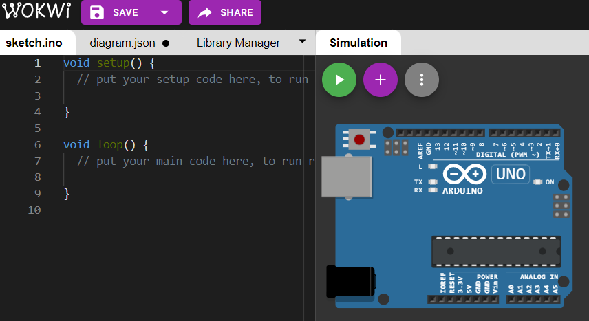
Start an empty Arduino UNO project
Click this link to open a new Arduino UNO project on the simulation window with empty setup() and loop() functions.
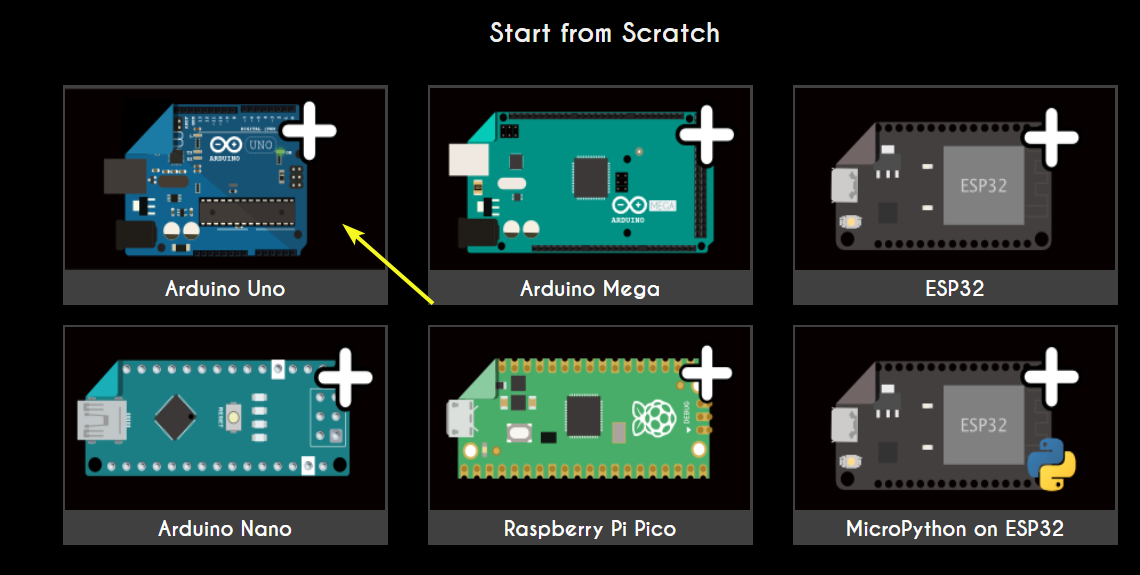
Alternatively, you can go to Wokwi’s home page, then scroll down to the Start from Scratch section. From here, click the Arduino Uno board.
Add the Wokwi Logic Analyzer
- Click the plus icon in the simulator window's upper left corner.
- Enter “logic analyzer” in the search bar. The search results will update as you type.
- Select “logic analyzer” from the search results.
Connect the Logic Analyzer
Connect the logic analyzer’s GND pin to the Arduino’s GND pin.
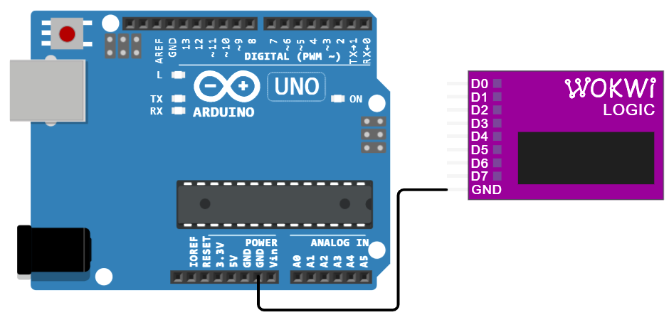
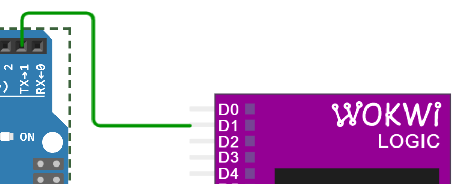
Arduino UNO’s second pin, TX→1, is the UART transmit (Tx) pin. The messages you send using Serial.Println() commands will transmit through this pin. It can be connected to the logic analyzer through any of the eight data pins: D0 - D7. For this example, I’ll use D1.
Run the Simulation
Run the simulation for 3-5 seconds. During simulation, the logic analyzer will display the number of recorded samples.
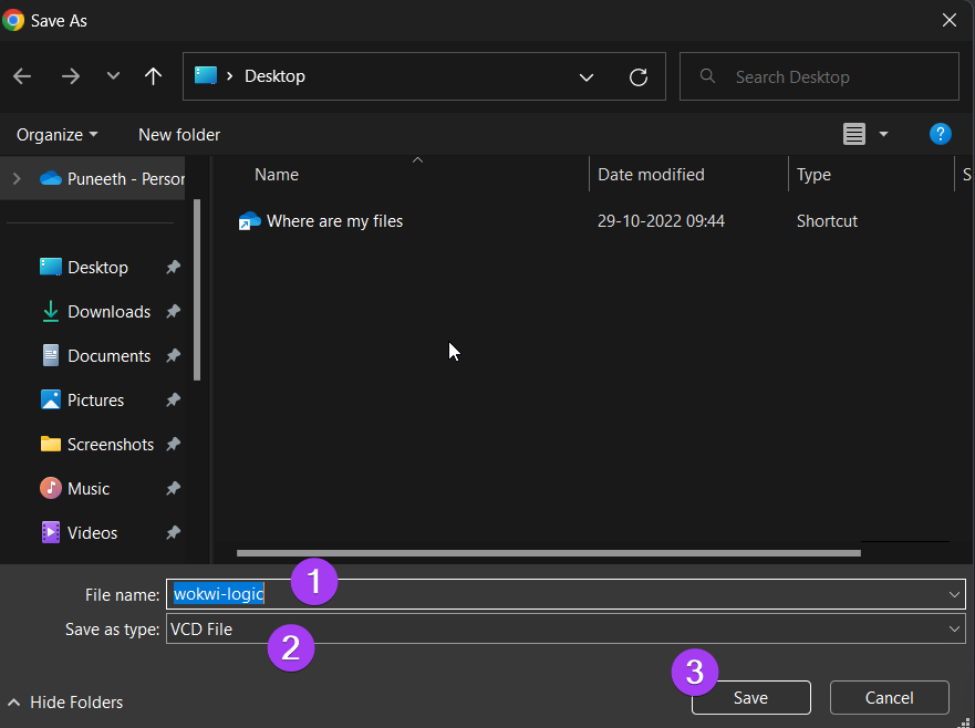
Stop the simulation. You’ll be prompted to save the log file. Your computer system’s file explorer will pop up. Navigate to the location where you want to save the log file and, if you prefer, edit the “wokwi-logic” default name. Once done, click the “Save” button.
Install PulseView to view the VCD file
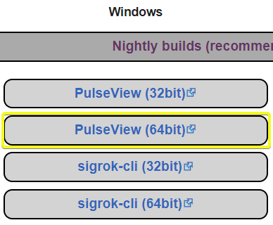
The PulseView software will be used to import the logged data. Click this link to visit Sigrok, where you can download the software. Choose the correct version for your PC to start the download. Install the software after downloading.
View the log file in PulseView
To view the log file, open PulseView. Then follow the steps below:
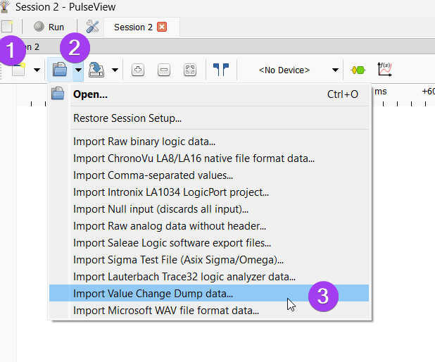
- Start a new session by clicking the “Create New Session” button at the top left corner, which looks like a blank notebook.
- Click the “Open” drop-down button, then select “Import Value Change Dump Data” from the options. Your file explorer will pop up.
- Navigate to the location where you previously stored the log file. Double-click the file to load it.
The window below will pop up after you’ve loaded the file.
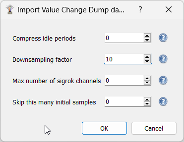
The Downsampling factor value can be adjusted to your preference. The higher the number, the faster the processing will be. Please take a look at the documentation on the Wokwi logic analyzer to learn how to choose the number correctly.
Click the “OK” button to proceed.
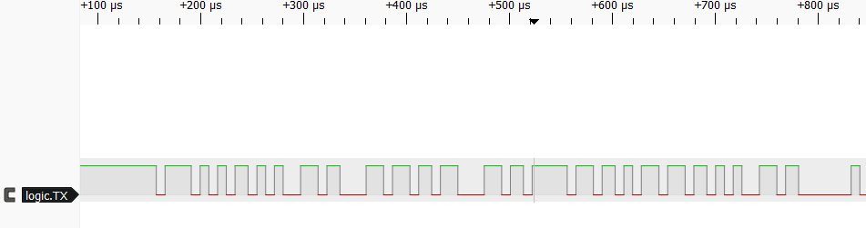
The data line transitions similar to the image below will appear.
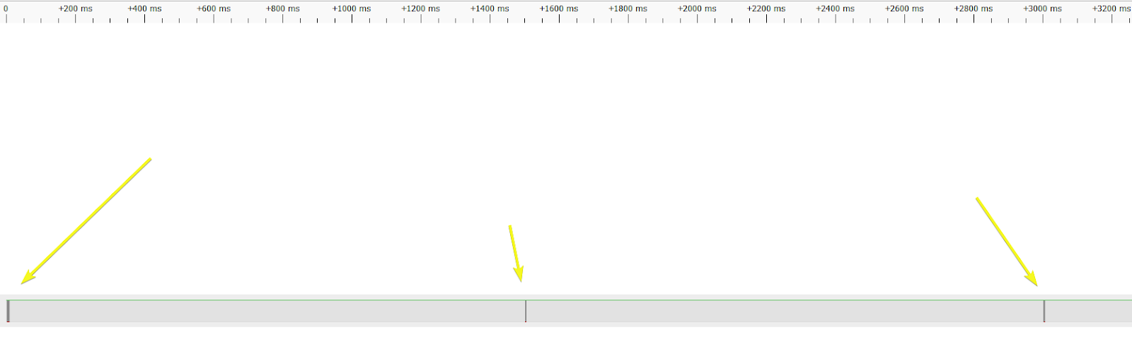
You can zoom in further within the data region to get a good view of the signal.
What does the signal represent?
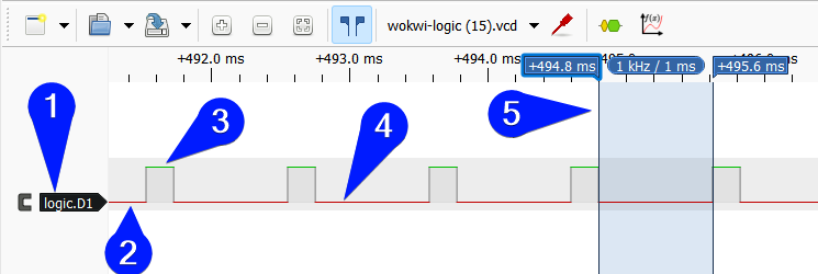
The image below highlights the logic analyzer's features.
- The signal name. You can click on the label to change it. For example: I would rename the transmit line of UART to
UART-Tx. - The signal to be analyzed. The color red represents the logic 0 or “low” state. In practical application, it will be zero volts. The logic high signal state is represented in green color.
- Logic high state ( 5 V, in case of Arduino UNO)
- Logic low state (0 V )
- The cursor option helps you to measure the pulse width, clock frequency, the time duration between two events, etc.
Note: The transition is in gray. When the signal transitions from logic 0 to logic 1 state, transitioning part of the signal is called a rising edge. Meanwhile, the signal transitioning from logic 1 to logic 0 state is called a falling edge.
Step 7: Adding the Protocol analyzer
The protocol analyzer will make reading the data easier. Here’s how to add it:
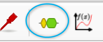
- Click the “Add protocol decoder” button at the top. This is the yellow and green icon (see image above)
- The “Decoder Selector” pane will slide into the right-hand side of the screen.
- Type UART on the Decoder Selector’s search bar. Then, double-click UART from the search results.
- A UART row will be added below the logic TX row.
To measure the pulse width, click the start point and drag it to the end point of the pulse.
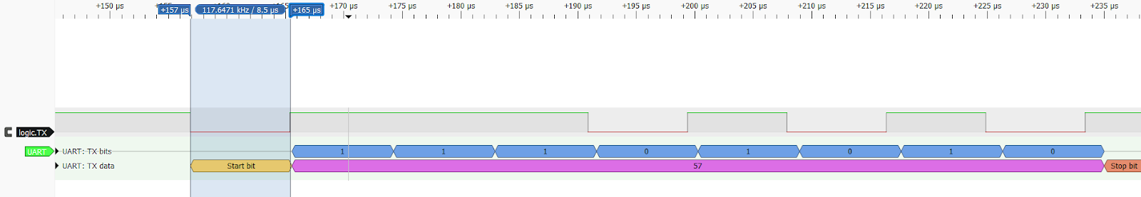
To change the data display (binary, hex, ASCII, etc.), double-click the protocol analyzer UART label (color green option in the image above).
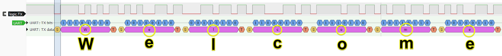
The Wokwi Logic analyzer helps you read messages to and from UART devices. In our example, we transmitted the text below as the first UART message.
Serial.println("Welcome to the Serial Playground!");The message is decoded in the image below.
Conclusion
In this article, we observed UART messages. I hope you learned how to add a logic analyzer to the Wokwi simulator and view the data easily. In part 2 of the article, we will learn more about UART (parity, data length, and baud rate).
If you have any feedback or suggestions to make the simulator more helpful, you are invited to connect with us on Facebook, Discord, and Twitter.