ESP32 JTAG Debugging using Raspberry Pi
ESP32 Hardware Debug: OpenOCD on Raspberry Pi w/GDB, ESP-IDF, and Visual Studio Code

In this blog, you'll learn how to set up a Raspberry Pi as a JTAG debugger for the ESP32. I'll then show you how to use GDB and even Visual Studio Code to debug your ESP32 programs using this setup.
I tested this setup on Raspberry Pi Model 3B+, but I believe it'll work with other hardware versions as well.
The first step would be to set up OpenOCD, a software chip debugger. It implements common debugging protocols, such as JTAG used by the ESP32.
Compiling OpenOCD on the Raspberry Pi
Run the following commands to make sure you have all the necessary tools on your Raspberry Pi:
sudo apt-get update
sudo apt-get install -y git make pkg-config autoconf libtool libusb-1.0-0 libusb-1.0-0-dev
Great! Now, let's get the source code for OpenOCD with ESP32 support and build it:
git clone https://github.com/espressif/openocd-esp32 ~/openocd-esp32
cd ~/openocd-esp32
./bootstrap
./configure --enable-sysfsgpio --enable-bcm2835gpio
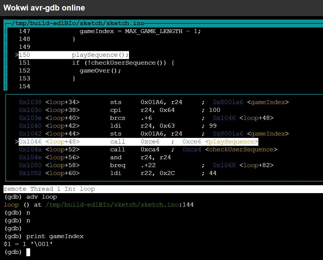
makeThis is going to take a while, so it's a great opportunity to get familiar with GDB. Or educate yourself about the internals of AVR.
Note the extra flags for the configure command: --enable-sysfsgpio --enable-bcm2835gpio.
They let OpenOCD use the Raspberry Pi's GPIO for talking JTAG with the ESP32.
Connecting the Raspberry Pi to the ESP32
You'll need 5 wires:
| Raspberry Pi GPIO | ESP32 Pin | Signal Name |
|---|---|---|
| GND | GND | Ground |
| 25 | GPIO14 | TMS |
| 10 | GPIO12 | TDI |
| 9 | GPIO15 | TDO |
| 11 | GPIO13 | TCK |
Or, if you prefer a diagram:
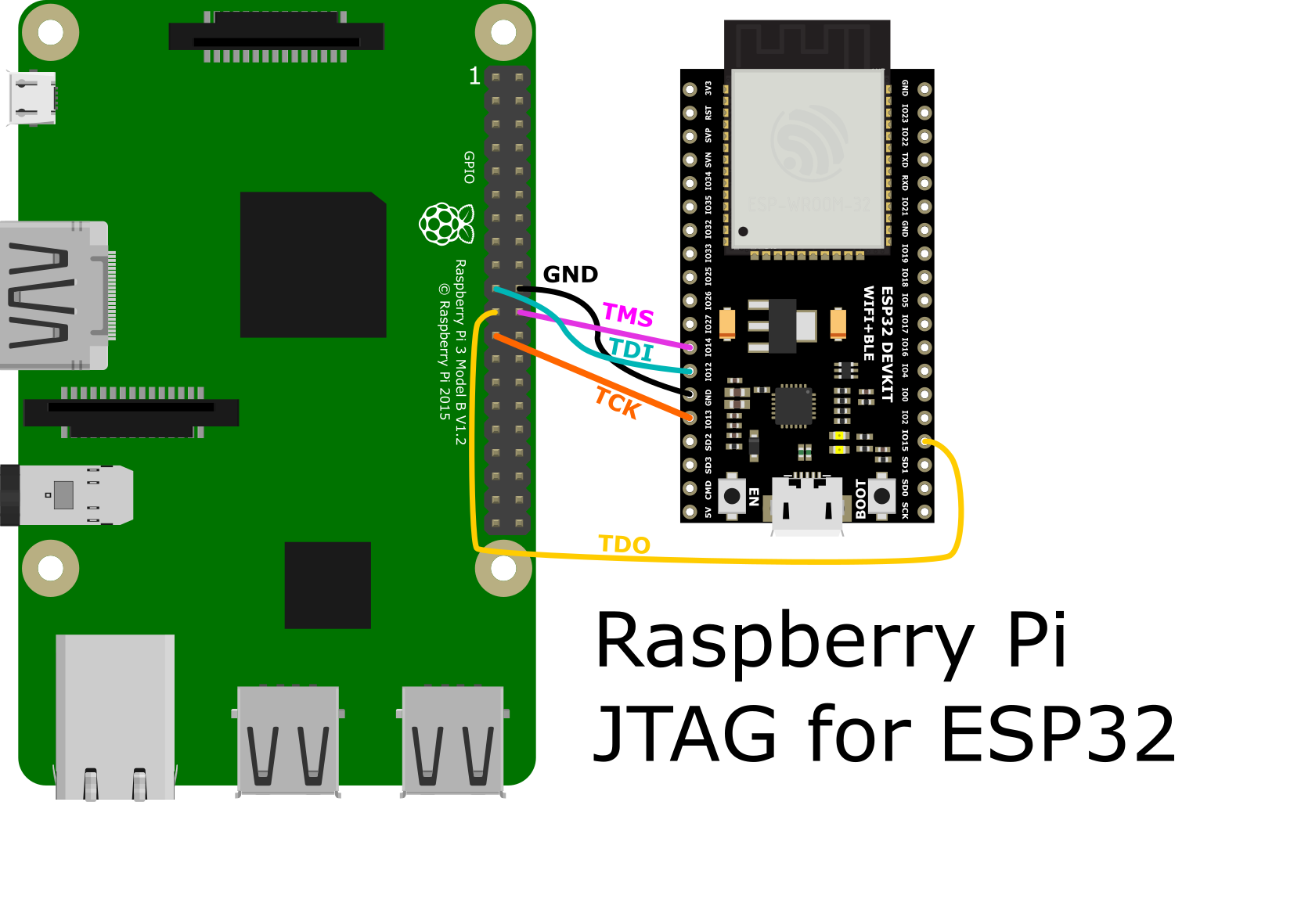
Note that you can change the Raspberry Pi pin assignments by editing ~/openocd-esp32/tcl/interface/raspberrypi2-native.cfg. Specifically, this is the line where the pin numbers are defined (TCK, TMS, TDI, and lastly TDO):
bcm2835gpio_jtag_nums 11 25 10 9The ESP32 drawing was taken from TD-er, licensed under the MIT license.
Running OpenOCD
You have to options here: either install OpenOCD globally on your system, or run it locally from the build folder.
Installing OpenOCD Globally
Run the following command:
sudo make installThen start OpenOCD:
openocd -f interface/raspberrypi2-native.cfg -f target/esp32.cfg -c "adapter_khz 1000"Running OpenOCD from the build folder
To run OpenOCD without installing it on your system:
cd ~/openocd-esp32
sudo OPENOCD_SCRIPTS=$PWD/tcl src/openocd -f interface/raspberrypi2-native.cfg -f target/esp32.cfg -c "adapter_khz 1000"
We run OpenOCD as root to give it direct access to the Pi's GPIO pins.
Did it work?
If everything went well, you should see output similar to the following:
Open On-Chip Debugger  v0.10.0-esp32-20210401 (2021-04-08-23:12)
Licensed under GNU GPL v2
For bug reports, read
        http://openocd.org/doc/doxygen/bugs.html
BCM2835 GPIO nums: swclk = 11, swdio = 25

adapter speed: 1000 kHz

Info : Listening on port 6666 for tcl connections
Info : Listening on port 4444 for telnet connections
Info : BCM2835 GPIO JTAG/SWD bitbang driver
Info : JTAG and SWD modes enabled
Info : clock speed 1001 kHz
Info : JTAG tap: esp32.cpu0 tap/device found: 0x120034e5 (mfg: 0x272 (Tensilica), part: 0x2003, ver: 0x1)
Info : JTAG tap: esp32.cpu1 tap/device found: 0x120034e5 (mfg: 0x272 (Tensilica), part: 0x2003, ver: 0x1)
Info : esp32.cpu0: Debug controller was reset.
Info : esp32.cpu0: Core was reset.
Info : esp32.cpu1: Debug controller was reset.
Info : esp32.cpu1: Core was reset.
Info : Listening on port 3333 for gdb connections
If you see an error, check your connections. You can also try setting a lower adapter_khz value in the openocd command. 1000 works well for me, but your mileage may vary.
GDB Debugging with ESP-IDF
ESP-IDF doesn't support remote debugging out of the box. The easiest workaround is setting up an SSH tunnel, so that local post 3333 is forwarded to the Raspberry Pi:
Setting up an SSH Tunnel (Recommended)
Run the following command on your development machine:
ssh -N -L 3333:raspberrypi:3333 pi@raspberrypiReplace raspberrypi with the IP address of your Raspberry Pi. You mean need to enter a password (the default one is "raspberry", but I truly hope you changed it!)
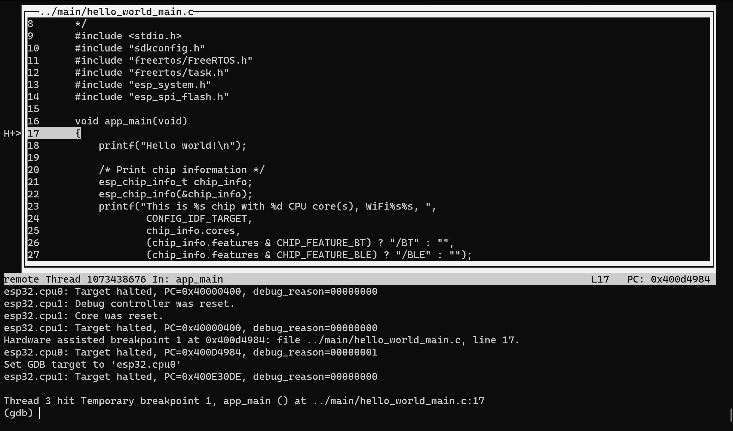
Then, start GDB by running idf.py gdb in any ESP32 project directory. GDB should connect to the OpenOCD running on your Raspberry Pi, and stop in the first line of your app_main() function.
The output show look like:
uri@JONI:~/esp-idf/examples/get-started/hello_world$ idf.py gdb
Executing action: gdb
GNU gdb (crosstool-NG esp-2020r3) 8.1.0.20180627-git
...
esp32.cpu1: Core was reset.
esp32.cpu0: Core was reset.
esp32.cpu0: Target halted, PC=0x40000400, debug_reason=00000000
esp32.cpu1: Core was reset.
esp32.cpu1: Target halted, PC=0x40000400, debug_reason=00000000
Hardware assisted breakpoint 1 at 0x400d4984: file ../main/hello_world_main.c, line 17.
esp32.cpu0: Target halted, PC=0x400D4984, debug_reason=00000001
Set GDB target to 'esp32.cpu0'
esp32.cpu1: Target halted, PC=0x400E30DE, debug_reason=00000000
...
Thread 9 hit Temporary breakpoint 1, app_main () at ../main/hello_world_main.c:17
17      {
(gdb)
Congratulations! You have got a working setup for debugging ESP32 code!
You can also run the text user interface (TUI) of GDB, by running idf.py gdbtui, or start a web-based interface by running idf.py gdbgui.
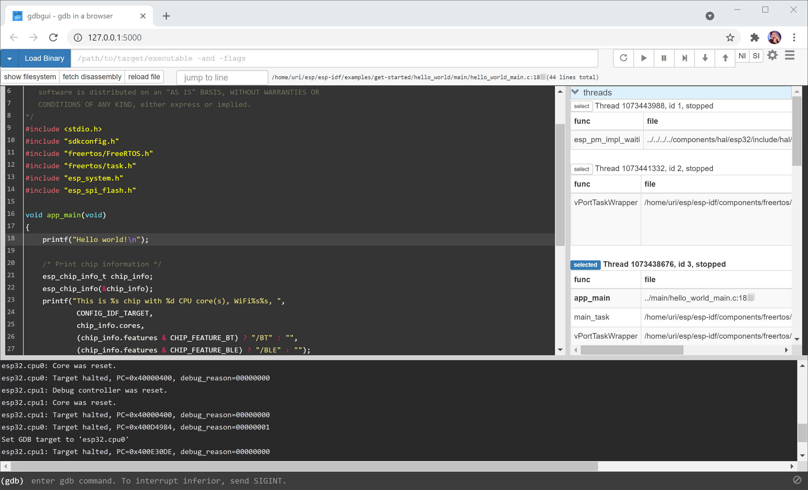
Patching ESP-IDF (Alternative)
Alternatively, you can patch ESP-IDF and tell it to connect to the Raspberry Pi instead of the local machine.
Go to the ESP-IDF directory and open tools/idf_py_actions/debug_ext.py in a text editor. Then search for target remote :3333 and change it to include your Raspberry Pi's IP address, e.g. target remote 192.168.1.101:3333 .
OpenOCD will not accept remote connections by default. To change this, add -c "bindto 0.0.0.0" to the OpenOCD command line.
Now proceed to run idf.py gdb (or gdbtui / gdbgui as described above)
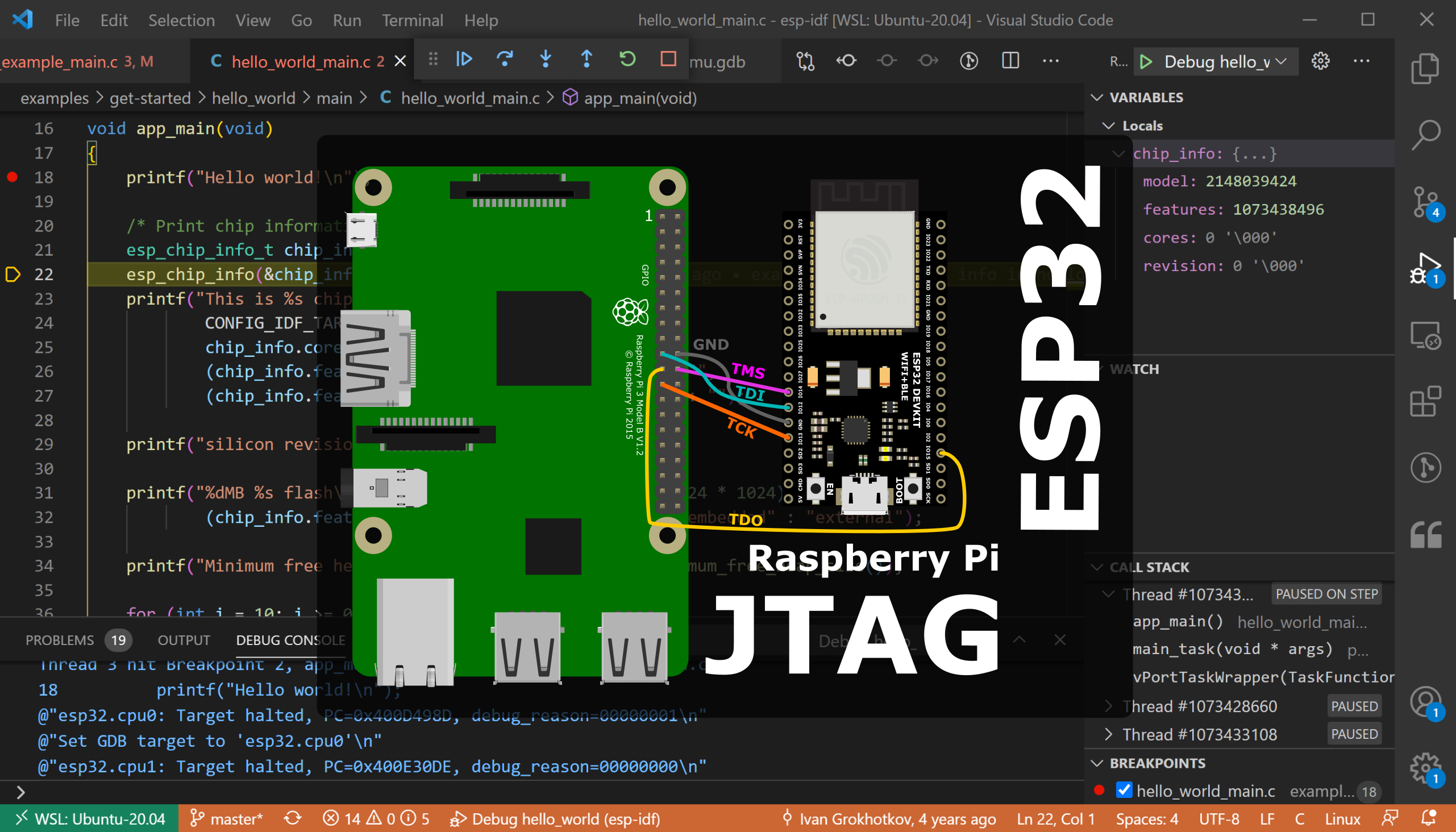
GDB Debugging with VSCode (Visual Studio Code)
This is my favorite setup!
First, make sure you have the C/C++ Extension for VSCode.
Next, open your project (or the ESP-IDF directory) in VSCode, and create a launch.json file:
{
  "version": "0.2.0",
  "configurations": [
    {
      "name": "Debug hello_world",
      "type": "cppdbg",
      "request": "launch",
      "program": "${workspaceFolder}/examples/get-started/hello_world/build/hello-world.elf",
      "cwd": "${workspaceFolder}",
      "MIMode": "gdb",
      "miDebuggerServerAddress": "raspberrypi:3333",
      "miDebuggerPath": "/home/uri/.espressif/tools/xtensa-esp32-elf/esp-2020r3-8.4.0/xtensa-esp32-elf/bin/xtensa-esp32-elf-gdb"
    }
  ]
}
You'll need to customize some of the configuration options:
- Set
programto the path of your ELF file. The ESP-IDF usually writes the ELF file inside thebuilddirectory of your project. - Change the
miDebuggerServerAddressto include the IP address of your Raspberry Pi (e.g.192.168.1.101:3333) - Change the
miDebuggerPathto point the xtensa-esp32-elf-gdb binary. The ESP-IDF includes a copy of this GDB version, but you can also download it separately from their GitHub repo.
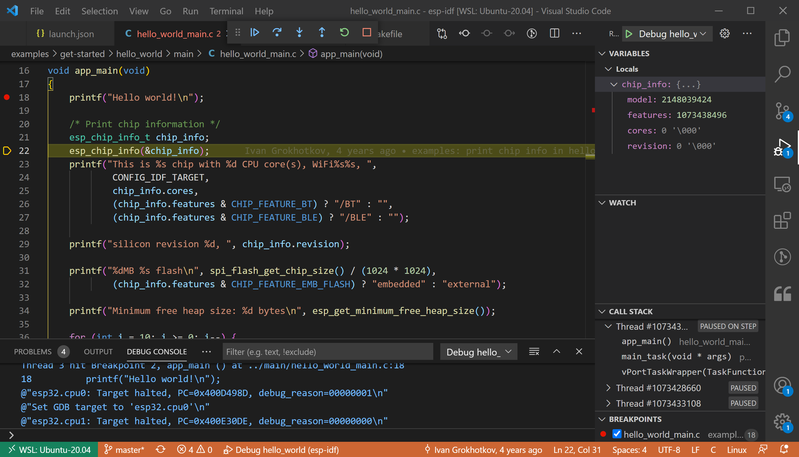
Press "F5" to test your configuration. You can set breakpoints (ESP32 supports 2 hardware breakpoints), and then restart your program by going to the Debug Console and typing:
`monitor reset halt
`continue
Voila! Now you can use Visual Studio code to debug your ESP32 applications!
Also, don't forget to take a look at our GDB Cheatsheet:
 Uri Shaked