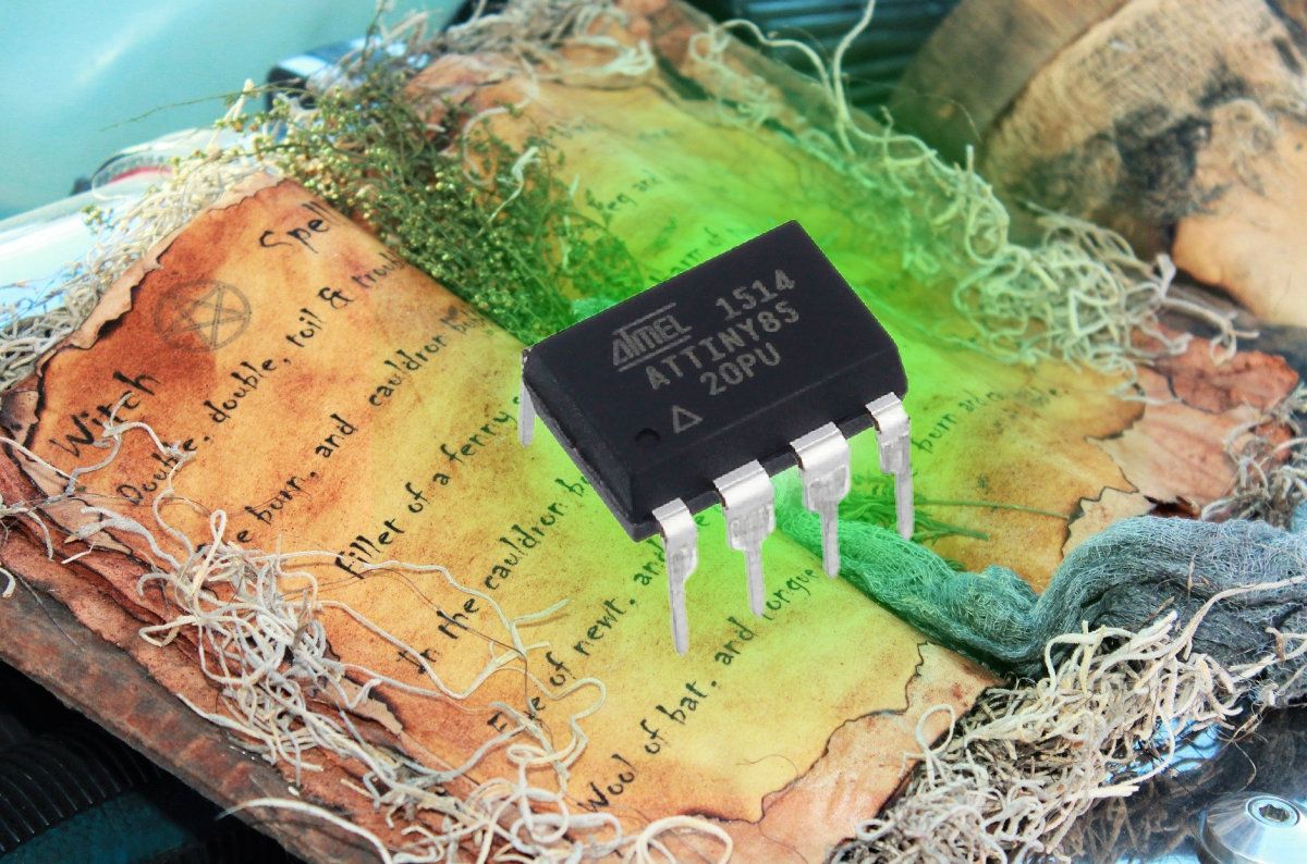
Removing a Curse from ATtiny85 Fuses
I bricked my ATtiny85, and even High-Voltage Serial Fuse programming couldn't save the day... This is what happened:

You are in the middle of working on an exciting project with ATtiny85. All of the sudden, it stops responding - and you are no longer able to program it or upload new code.
I found myself in this frustrating situation while working on The Skull, a new hardware CTF challenge with a spooky twist. To be honest, it was a bit of my fault: I left some pins connected to an Uno board while trying to program the chip, and they probably interfered with the process.
So I was a bonehead and ended up with a broken skull. Great!
Now, let me share with you how I fixed that. Who knows, you might brick your ATtiny85 and this will save your day.
The Cursed Fuses ?
ATtiny chips (and in general, microcontrollers from the AVR family) have some configuration bytes called fuses. They control various aspects of the microcontroller such as the clock source (internal/external), chip reprogramming, debugging interface, etc.
It's very easy to shoot yourself in the foot by disabling the SPI (serial programming interface), disabling the reset pin (which is required for programming), or just choosing the wrong clock source. Microchip even created a dedicated page for all the things that can go wrong.
So my ATtiny's fuses probably got cursed with bad values that disable programming... Now what?
Enter High-Voltage ⚡
Fortunately, even when things go wrong, there's a special programming interface built into the chip, high-voltage serial programming (HVSP), or "god mode" as I call it. It lets you reprogram the chip even if you disabled the reset pin and the standard serial programming interface.
However, HVSP, as the name suggests, requires a non-trivial setup: you have to apply 12V to the reset pin. It's like a small backdoor built into the chip, to help you fix things when hell breaks loose and the chip stops talking to you.
I'm not the first to face this situation, so quick googling found a handy tutorial which explains how to build this kind of HVSP programmer with just one more ATtiny chip, 2N3904 transistor, an LED and some resistors. It even included the code that would reset the fuses to their original values.
ATtiny45 has cursed fuses, trying to fix with HVSP ⚡ pic.twitter.com/7vUFjuQ2dq
— The Skull (@skullctf) November 10, 2020
The idea is simple: you upload the code to a second ATtiny (we'll call it the HVSP programmer from this point), wire it to the first one (the bricked ATtiny), provide 12V for the transistor, power on the circuit, and observe the result:
- LED goes on briefly, then off: GREAT SUCCESS
- LED blinks slowly (1hz): ATtiny could not be identified
- LED blinks fast (5hz): ATtiny fuse values were not updated correctly
After programming the second ATtiny and connecting everything, I switched it on and...
Great Success? ?
No, it wasn't a great success. I got an unexpected result: the LED would just stay on, which is definitely not an expected result.
Looking as it closer, I realized it was just blinking very fast. Apparently, the HVSP programmer's ATtiny had the clock configured incorrectly, so delay() did not work as expected causing the LED to blink really fast, which seemed as if it was just on all the time.
I fixed that, reuploaded the HVSP code to the ATtiny, and gave it another shot. This time, the LED blinked fast, at about 5hz - meaning, it could identify the chip, but could not update the fuses? huh?
To make sure my setup was correct, I tried recovering another ATtiny, which I intentionally "bricked" by disabling the reset pin, and the HVSP recovery succeeded: the LED went briefly on, then stayed off.
So obviously, something strange was going with that chip on the skull: the HVSP programmer could identify it, but couldn't set the fuses? huh?
Comparing Signals
At this point, I decided to take a look at the communication that was going between the HVSP programmer and the bricked ATtiny's. I used a Saleae USB logic analyzer to record the signals so I could compare them.
The HVSP programmer uses a proprietary protocol over 4 I/O pins:
- SDI - Serial Data Input
- SII - Serial Instruction Input
- SDO - Serial Data Output (this is how we get data back from the ATtiny)
- SCI - Serial Clock Input
To make things even more challenging, each frame is 11-bit wide (you could also say these are 8-bit frames over 11 clock pulses):
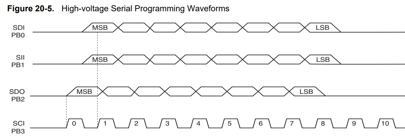
But the fun doesn't end here: the SDO line has an additional role. Not only it carries responses from the ATtiny to the HVSP programmer, it also indicates if the ATtiny is busy (when LOW) or ready to accept commands (when HIGH).
When looking at the signals of the ATtiny that could not be recovered and comparing with the one that I could recover, there's an apparent difference:
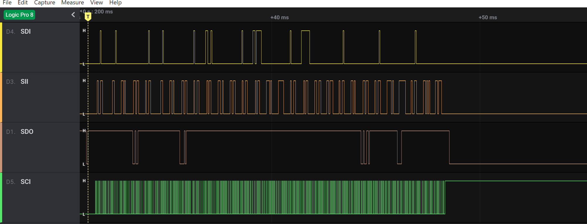
You can see the the recoverable ATtiny kept the SDO line low for about 4ms three times (these are the large "pits" in the pink line). It's also apparent that the programmer stopped sending it clock signal (the green jumpy line) during these times.
If we look at the HVSP programmer's code, we can see it works as follows:
- Enter HVSP programming mode
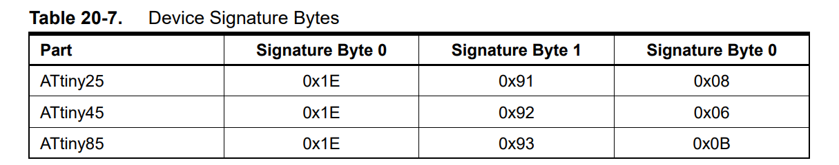
- Read the chip's device signature bytes (two bytes that identify the chip model) and compares them with a list of known signatures
- If the signature doesn't match any of the known signatures, then stop the process and flash the LED slowly (at 1HZ)
- Otherwise, write the three fuse bytes, setting them to the factory default values
- Read back the value of the fuses and compare them with the expected values. If there's a match, turn the LED off.
If the values don't match, blink the LED rapidly (5hz).
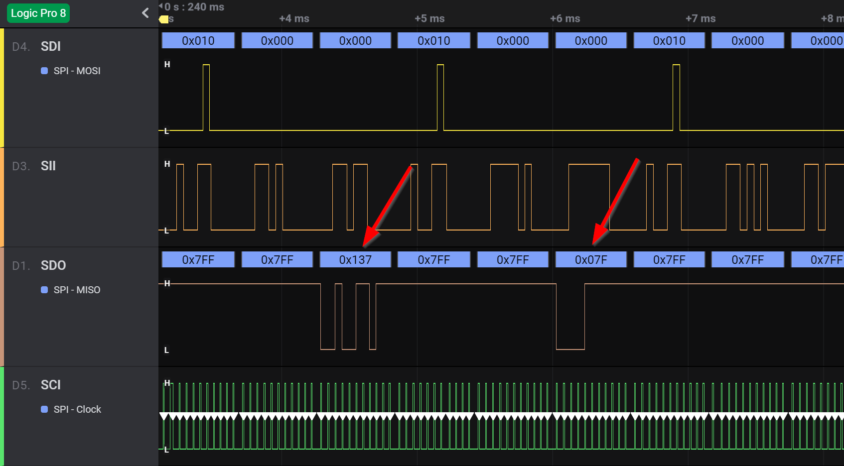
And here is what the steps look into in the capture:
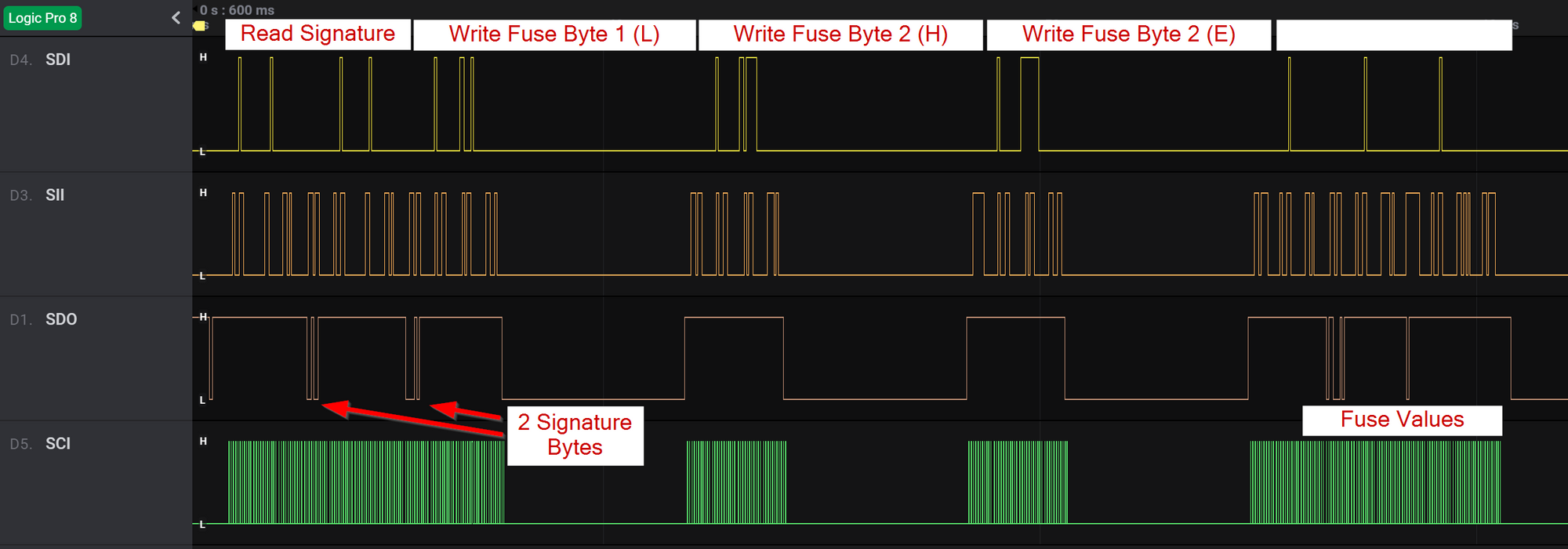
It should now be easier to see the pattern: whenever the HVSP programmer writes a Fuse byte, the recoverable ATtiny keeps the SDO line low for a short while. That's the time it takes to actually flash the content of that Fuse byte.
This didn't happen in the bricked ATtiny. While it did respond to the Read Signature and Read Fuse Value commands, it never kept the SDO line low after a write fuse byte program:
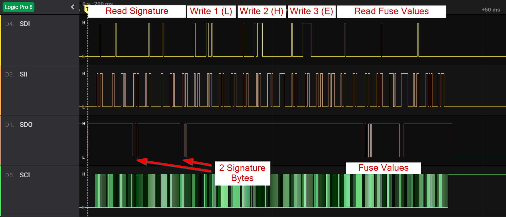
You can see that the 2 signature bytes are the same for both chips. However, the writes for the bricked chip are much shorter, without the delay, and the Fuse values read during the verification process seem different.
At this point I really wanted to know:
What these Fuse bytes in the bricked chip contained?
Decoding the Fuse Bytes
The software I was using, Saleae Logic 2, comes with many built-in protocol analyzers. However, the HVSP protocol wasn't supported out of the box, so I started tinkering with the existing analyzers.
Eventually, I found a creative way to take advantage of the SPI analyzer. I configured it to use 11-bit frames, and selected SDO for the MISO signal, SCI for the clock signal, setting data to be read on the clock's trailing edge (CPHA=1):
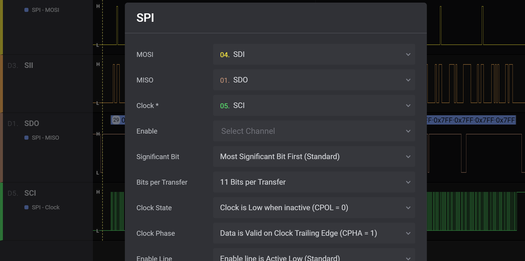
One last thing, I had to shift-right the decoded values by 3 bits, to discard the extra 3 clock pulses at the end of each frame. This is what the decoded data looked like:
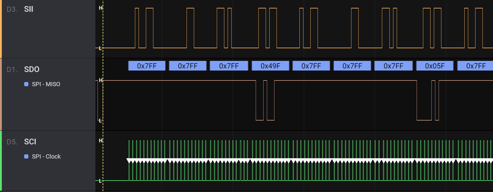
After taking the two decoded values and shifting them right by 3 bits, we got 0x93 0x0B, which happen to match the signature bytes for ATtiny85:
Following the same process for the fuse bytes, we can now decode them:
And after applying the 3-bit shift we get 0x26 and 0x0f. We can paste these values into the ATtiny fuse calculator, and see what they dictate:
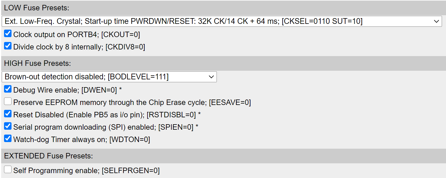
We can see the Reset was disabled, the clock source was set to External Low-Frequency Crystal, and the Debug Wire was enabled. These 3 settings all interfere with chip programming!
But the mystery remained: why couldn't I reset the fuses on the bricked ATtiny using the HVSP programmer I built?
Unlocking the Mystery of the Fuses ?
I dug through long-forgotten threads in the AVR Freaks and Arduino forums, read through the datasheet, as I suddenly realize what was happening:
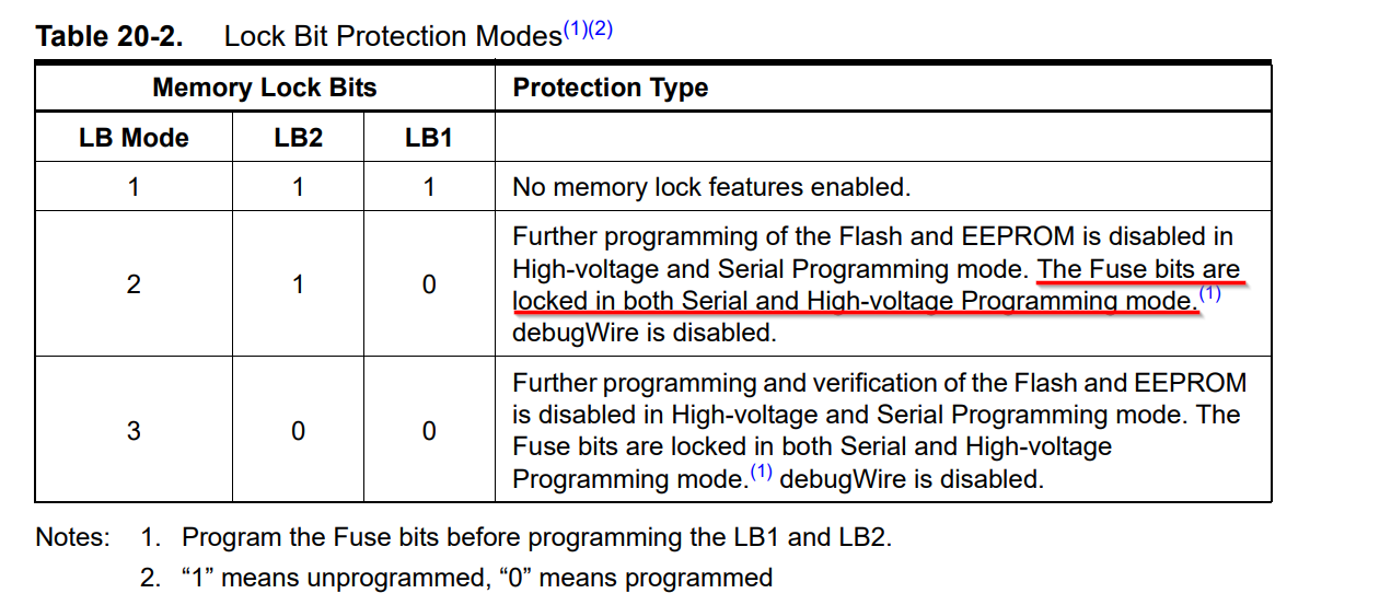
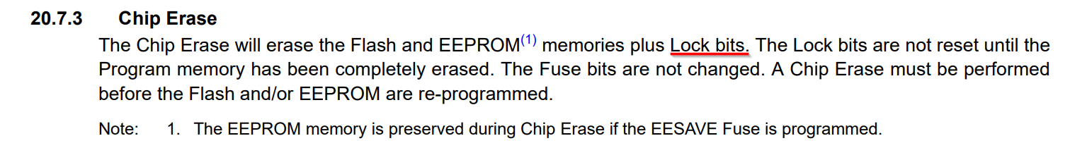
It seems like while bricking my ATtiny, it also got its Lock Bits programmed. These Lock Bits disable further programming of the chip, including the fuses.
Luckily, the datasheet mentioned a workaround: the Chip Erase command.
Chip Erase: Removing The Curse ?
Following this epic discovery, I went on to make an action plan:
- Chip Erase
- Reset the Fuses
- Profit!
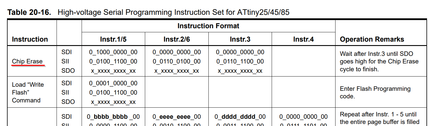
Consulting the datasheet (again), I found the code for the Chip Erase command at the top of the High-voltage Serial Programming Instruction Set table:
Happily, I coded into into a neat Arduino function:
// See table 20-16 in the datasheet
void chipErase() {
shiftOut(0b10000000, 0b01001100);
shiftOut(0b00000000, 0b01100100);
shiftOut(0b00000000, 0b01101100);
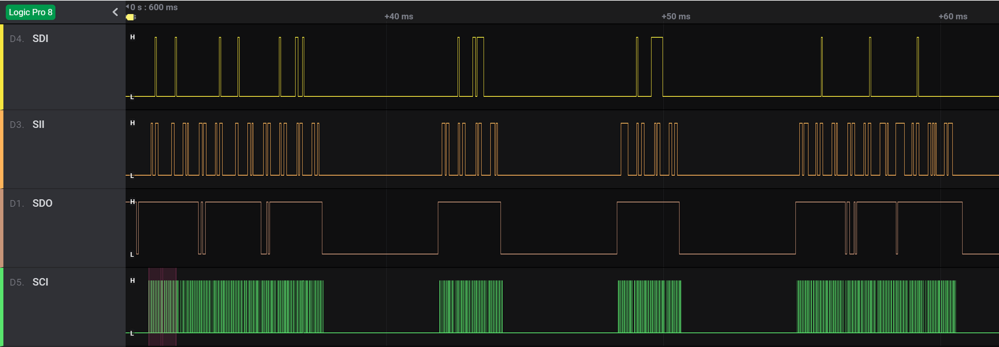
}Calling this new function just before setting the fuse bits. I flashed the new code to my HVSP programmer, plugged everything and...
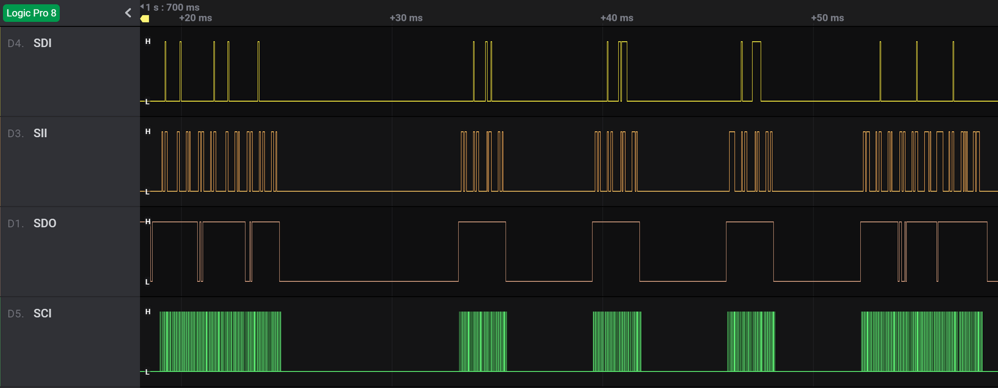
You can see that we now have 4 "pits" in the SDO line. The first, longer one, is that time the bricked ATtiny was busy executing the Chip Erase command. The 3 following pits are were the fuses were reprogrammed. At that point, the bricked ATtiny was no longer bricked.
The Skull was resurrected, hooray! ?
Show Me The Bytes!
Well, you asked for it. I uploaded all the Logic Analyzer Recordings to a GitHub repository, so you can play around (try the SPI trick, etc). You'll can open them with the Logic 2 Software (you can run it without owning the Saleae hardware).
I also decided to share the modified HVSP firmware with the new Chip Erase function, so the next person who needs to revive a bricked ATtiny chip doesn't have to figure it out the hard way like I did.
Now, that the ATtiny is back to life, I can continue hacking on The Skull's firmware. Here, I'll let you peek at the code: