Inside The Bulb: Adventures in Reverse Engineering Smart Bulb Firmware
How we extracted a smart WiFi bulb firmware using a Dremel tool, Soldering Iron, Raspberry Pi, flashrom, and IDA


Following the Reverse Engineering a Smart Light Bulb post, I got contacted by Eyal, a member of the TAMI community, asking if we could meet up and try to reverse engineer a Xiaomi Yeelight WiFi Bulb he has recently purchased.
TAMI stands for Tel Aviv Makers International, a hacker space for Makers based in Tel Aviv. The TAMI hacker space contains a ton of electronics lab equipment and components, a wood workshop, metal workshop, CNC machine, textile machines, and pretty much all the necessary tools you could think of. In addition to the physical space, TAMI also has a very active Facebook group with over 4,000 Israeli makers. You will find there frequent discussions about electronics, RF, manufacturing, lab equipment, mechanical engineering, plumbing, whatever…
Eyal and I met at TAMI Tel Aviv and made a plan to understand the inner working of the bulb. After a short discussion, we decided to go with a more physical approach this time: actually disassembling the bulb and attempting to read the firmware (the software that controls the hardware) directly from the chip.
We expected some AC-DC voltage conversion circuit, a few LEDs and a control circuit. We didn’t know what we were going to be able to get from the control circuit: we hoped we would be able to recognize the chip and be able to extract the code or even debug it while the bulb was running.
We managed to remove the plastic cover quite easily, which revealed the board with the LEDs:
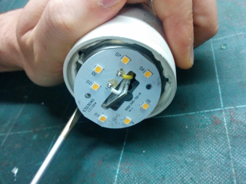
As you can see in the photo above, there are 7 high-power warm white LEDs, and there is a small circuit popping out from the middle. Removing this circuit required cracking the bulb shell, which we accomplished with some Dremel work:
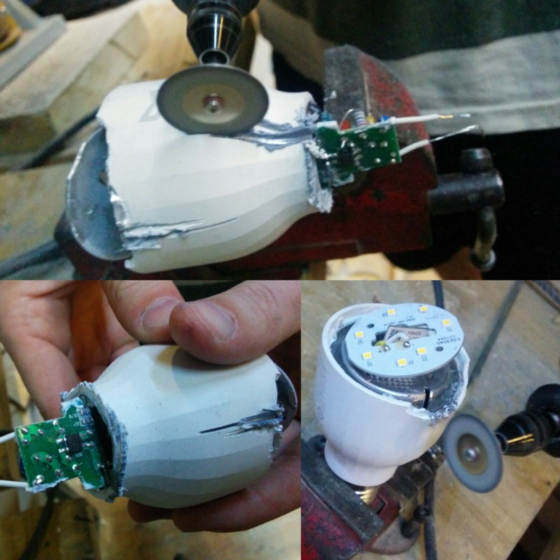
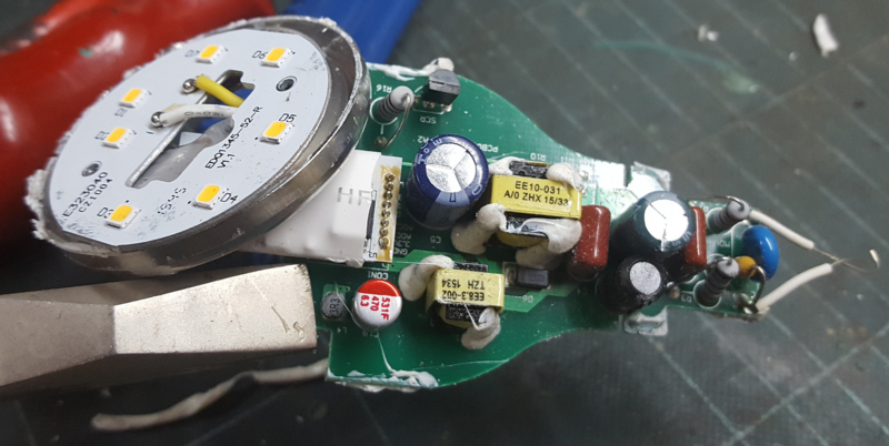
After removing the shell completely, Eyal and I finally gained access to all the inner parts of the bulb: the power supply circuit, the control circuits, and the LEDs circuit.
We concluded our first meeting by dining in a traditional Indian restaurant called 24 Rupee (which I highly recommended if you’re ever in Tel Aviv), and picked a time to meet again to try and extract the firmware.
???
Our next meeting was held in FabLab Hulon. FabLab is a worldwide network of maker spaces focusing on digital fabrication. They’ve got things like 3-D printers, laser cutters, milling machines, and electronics equipment, and they do special community projects, such as a Digital art workshop for blind and visually impaired children.
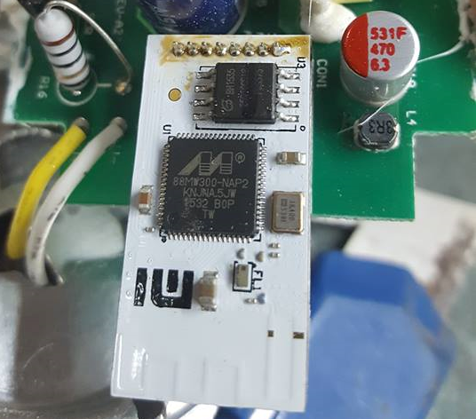
The goal of this meeting was to extract the firmware from the bulb. Using a magnifying glass, we managed to find the part numbers of the components on board. Quick googling revealed their identity:
- 88MW300 — A Marvell Wi-Fi Microcontroller system-on-chip (SoC)
- 25Q16BVSIG — 16M-Bit Serial Flash Memory Chip
Figuring out that the CPU was using the ARM architecture was really handy. There are plenty of tools for working with ARM CPUs, including a standard way of debugging them.
We desoldered the logic board (the white one) from the power board (the green one), and connected two of the pins to the power supply so we could to try and power it on later. Unfortunately, when we tried to do so, it started smoking… it appeared we created a short circuit somewhere along the way.
The moral of the story is that debugging the CPU in place was not an option.
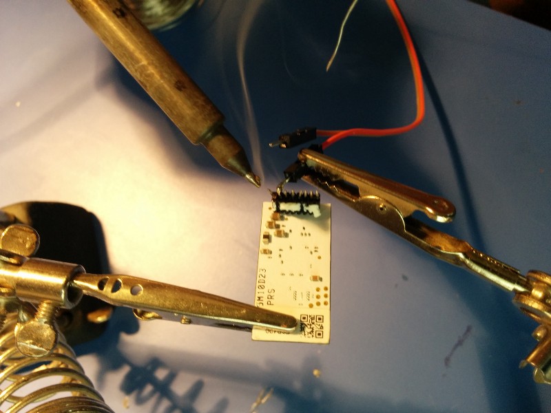
Fun Fact: 3 out of the 8 pins on the white board weren’t soldered, and since they were labeled “R,” “B,” “G,” that means they probably use the logic board for the RGBW version of the bulb, too!
Fortunately, the Flash chip (the ones that stores the firmware, i.e., the code that powers the smart bulb) was relatively easy to remove, so removed it we did.
The Flash memory chip is a standard serial flash, and fortunately, we had a Raspberry Pi board lying around. Raspberry Pi proved to be a very handy tool to have in one’s tool belt: it has saved the day several times when I needed to interface with custom hardware (especially when I was the one who built the custom hardware). In this case, we were able to find a tool called “flashrom” which could read and write from a serial flash connected to Raspberry Pi GPIO pins.
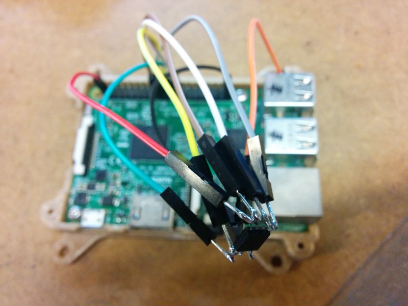
After installing Flashrom and connecting the Flash chip to the Raspberry Pi, we ran the following command:
flashrom -p linux_spi:dev=/dev/spidev0.0 -read yeerom.binAfter about a minute of stressful waiting, we were excited to see it actually work!
Finally, we had something we could work with: a 2MB dump file of the bulb’s firmware. That’s where the software part of our story begins…
???
So, we managed to extract the firmware from the bulb, but now what?
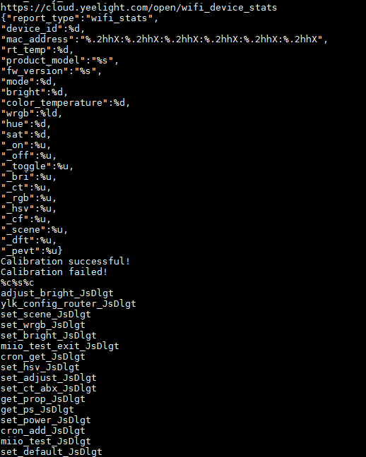
The first thing to do when you get a firmware file, is to run the strings utility on it. strings is a Unix command that extracts all the strings from the file. And there were plenty of strings in that file! For example, here is a the output when looking for all the strings which contain http:
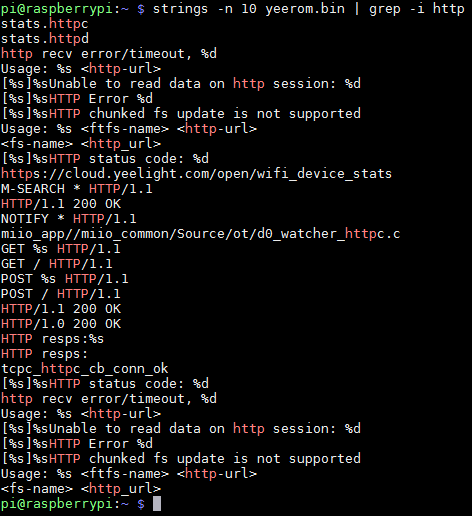
As you can see in the output above, the firmware code speaks the HTTP protocol, and it seems like one of the endpoints it talks with is https://cloud.yeelight.com/open/wifi_device_stats. This output was very encouraging — it seemed like we were on to something.
Other interesting things that we discovered, just by looking in the strings, were an SSL certificate, several JSON structures, and a list of strings that seem to be command names sent from the server, as you can see in the screen shot below:
This is what the decoded certificate looked like:
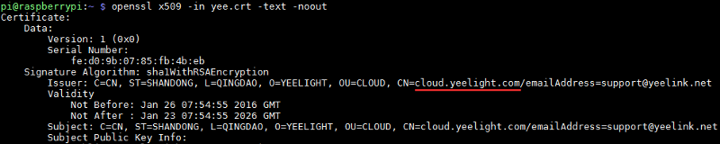
It definitely seemed like something was going on with cloud.yeelight.com, and having the certificate embedded into the firmware, it seems like they take security seriously — making sure that the bulb actually talks to their own server, and not an impersonator (this technique is called SSL public key pinning).
While we managed to discover some interesting bits of the bulb protocol, there is only so much you can figure out by just looking at the strings. The next logical step would be to try and actually read the machine code that powers the bulb.
We dumped the contents of the file using a Linux utility called hd (which stands for hex dump), and discovered it contained several sections, including one that seemed to be some kind of file system that indexes the other sections of the file:
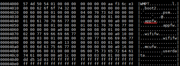
It seems like the firmware image holds two copies of the app firmware, the two copies of the WiFi firmware, some other sections, as well as a section using the user data (which later we discovered includes the name and password of the WiFi that we configured in the bulb before disassembling it, and the password appeared in plain text :-/ ).
However, we didn’t need to decode the structure of the table, as there were plenty of zero bytes separating the sections. Knowing this, we figured out that the actual firmware (one of the two copies) resides at offset 0xa000 and extracted it using the dd command:
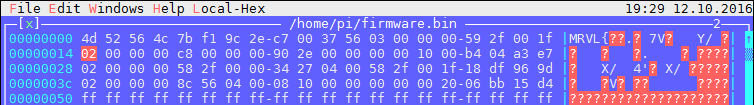
dd if=yeerom.bin bs=$((0xa000)) skip=1 count=7 of=firmware.binThen, I naively tried to load this .bin file into IDA, a popular tool for reverse engineering. I hoped that it would somehow recognize the format of this firmware, but to no avail: it seems like it is some kind of format specific to Marvell (if you look into the file, you can actually see the it starts with the following 4 bytes: MRVL).
I then decided to try and understand how to properly load the firmware. The beginning of the file looked as if it had some format, perhaps a table of sections and their offset into the file?
I decided to look online to see if I could find more about the 88MW300 CPU or this “MRVL” format. The information was scarce, but I did manage to find one open source SDK from Marvell, aiming to help developers easily create IoT-enabled devices using their chip and the Amazon cloud. Their SDK contained some samples that actually built these firmware files, using a tool called axf2firmware, which was also a part of the SDK. The table consists of 20 bytes entries, each of them with this structure (DWORD is little-endian 4 bytes integer):
DWORD magic;     // Always 0x2
DWORD offset;    // Offset into the file
DWORD size;      // Size of the section
DWORD address;   // Memory address where this section will be loaded
DWORD unknown;   // Probably some kind of checksum?
Thanks to this information, I could read the table of sections, and actually split them into different files, using the following Linux command:
dd if=firmware.bin bs=200 skip=1 | dd bs=11920 count=1 of=s1.bin
dd if=firmware.bin bs=12120 skip=1 | dd bs=1 count=272180 of=s2.bin
dd if=firmware.bin bs=284300 skip=1 | dd bs=4104 count=1 of=s3.bin
Thus, I ended with 3 files: s1.bin, s2.bin and s3.bin. Using the information from the table above, I knew which memory address these file go to when the firmware is loaded. I decided to try to combine these files into a single executable file using a format that can be loaded into IDA. I chose the ELF format, an executable file format used by Linux, as there is a lot of open source tooling and documentation for that format.
First, I installed the arm binary utils to work with ELF files:
sudo apt-get install binutils-arm-none-eabiThen, I ran the following command to assemble all the different sections into a single ELF file:
arm-none-eabi-objcopy -I binary -O elf32-littlearm --set-start 0x134 --adjust-vma 0x100000 --binary-architecture arm --rename-section .data=.text,contents,alloc,load,readonly,code --add-section .text2=s2.bin --set-section-flags .text2=contents,alloc,load,readonly,code --change-section-address .text2=0x1f002f58 --add-section .text3=section3.bin --set-section-flags .text3=contents,alloc,load,readonly,code --change-section-address .text3=0x20000000 s1.bin firmware.elfThe command is quite long, and it took some hours of work to figure out all the bits and get it right, but basically, all it does is specify the 3 files containing the content of the actual section, the memory address where these sections should be loaded, the flags to set all these section as read-only code sections (so that they will be disassembled / decompiled), and an instruction to set the base memory address of 0x100000 and to start executing the code from offset 0x134. The resulting file will be called firmware.elf.
And Voila! I could load this file in IDA. Unfortunately, the code was still not making a lot of sense.
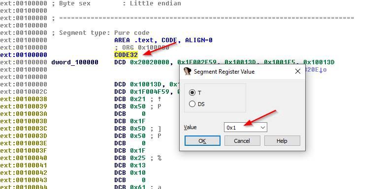
IDA interpreted the file as ARM machine code, as it should, but it turns out ARM processors have a special operating mode called “Thumb.” In Thumb mode, CPU instructions are encoded in two bytes (16 bits) instead of four bytes (32 bits).
This can be easily fixed by going to the very beginning of the file, looking for a line where it says CODE32, pressing Alt+G, and changing the value there to 0x1 (I am so lucky I have Google to figure these things out):
Following that, I got a long bunch of ARM assembly code. While IDA could automatically identify a bunch of functions in the code, it can’t tell you what these functions do. There is a nice trick however — in many cases, the firmware code contains debug prints that were put into place during the development of the code, and they can be very helpful in figuring out what the code does. After some digging, I managed to identify the printf function, and then I could find all the debug prints in the code by pressing “X”, which displays all the locations in the code where printf is used:

At this point, I had to leave the project — I felt like Eyal could take it off from here, and also had to leave to go present at AngularConnect. Eyal is now traveling in India, but he already ordered another Bulb, and plans to continue working on the project when he gets home.
I want to thank you, Eyal, for taking me on this fun adventure! I hope that the information presented in this post will also be useful for other adventurers wandering in the land of hardware and looking to get their hands on some firmware.
If any of the readers are interested in looking into the firmware and trying to figure out more, let me know! The more we take apart, reverse engineer, and share our knowledge of IoT devices, the more we, as a community, will be able to build super awesome stuff in the future.
So go forth, break things, and tell us how you did it!