Custom Chips? Yes Please
Create custom chips for Wokwi and extend the simulation using the C API

Introduction
Wokwi is a free browser-based embedded simulator. Wokwi currently has more than 100 parts available for simulation. Still, there’s a chance that the part you’re looking for is not available... yet! If that’s the case, you can always create a custom chip to function the same way as the part you’re looking for.
In this article, we’ll learn how to create a custom chip on Wokwi! Specifically, we’ll create the CD4052B chip, a multiplexer/demultiplexer IC. To accomplish this, we’ll take some pointers from a similar project.
Christ Schmidt has successfully created a custom chip on Wokwi to simulate CD4051B, a 3 to 8 Encoder/Decoder. We’ll go through his project first to understand the implementation before we move on to our main project.
To put it simply, we’ll learn the basics first 😎. Then, in the later part of this article, we’ll create a custom chip to simulate CD4052B!
Let's get started!
Breaking down CD4051B implementation

There are four files in the CD4051B project:
- sketch.ino
- Diagram.json
- cd4051b.chip.json
- cd4051b.chip.c
Arduino Sketch (sketch.ino)
The sketch.ino file contains the functions and instructions that Arduino will execute. You can either write the code in the editor window, or copy it from a different source then paste it in.
diagram.json
The diagram.json file is where you can modify the attributes of all the parts you’ve added in the editor window. Specifying the LED color or choosing the servo horn are some of the things you can do here. Its code also dictates how the added electronic components are connected to the Arduino UNO board. Their purpose is also indicated in this file.
cd4051b.chip.json
This JSON file declares the chip’s name and the associated pins. This is important as the chips interact with the simulator using these pins.
Let’s look at the file’s contents:
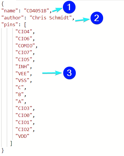
The code uses three commands:
namedeclares the chip’s name. The same name will appear on the chip. So choose wisely 😉authorthe name of the person who created the custom chip.pinsdefines the pins in the order in which they appear in the IC, in a counterclockwise order. Here’s an example to show how the pins will be placed in the IC:
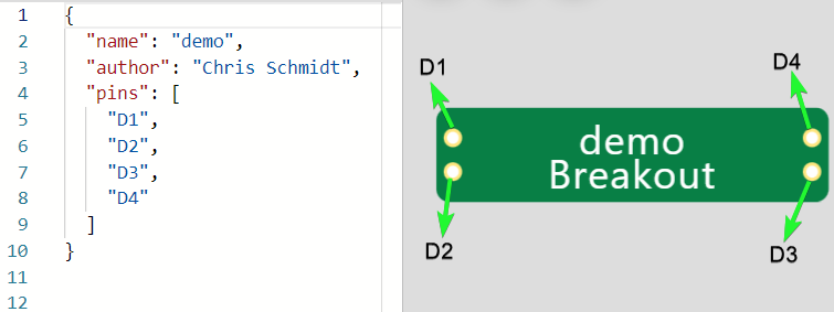
The example above creates an IC with four pins D1, D2, D3, and D4. The topmost pin is placed at the top left corner of the IC, then the following ones are placed in a counterclockwise direction. Hence, D2 is at the bottom left, D3 is at the bottom right, and D4 is at the top right corner.
This shows that the order in which you place the pins in the JSON file matters!
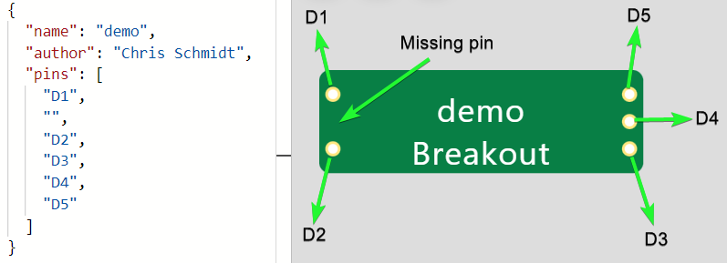
If you want to skip a pin, leave the space between quotes empty, as shown in the screenshot below.
Declaring Pins - One More Example
The pinout below belongs to a watchdog timer IC STWD100NYWY3F. It has five pins.

The JSON file will look similar to the screenshot below. Notice that there is an empty pin, indicated by the empty quotes, after WDI in the JSON file.
cd4051b.chip.c
The chip.c file is the heart of the custom chip, we where implement the logic of the chip. Usually, before writing any logic, we look for the datasheet of the chip that we want to implement. We'll start with the pin out diagram.
For the CD4051B chip, the pin designations are as follows:
Next, we'll look at the truth table for the chip is shown below. For now, look at the section for CD4051B (the top part). We’ll look at the CD4052B section later when we get to build the actual project.
Now, let’s talk about the code for this file, where we write the logic of the custom chip. We’ll discuss each block of code from top to bottom so you can understand the function of each one:
Include dependencies
#include "wokwi-api.h"
#include <stdio.h>
#include <stdlib.h>
The wokwi-api.h contains definitions of APIs you can use to build the custom chip functionality. You can also print debug messages onto the console. This helps you while you are building your custom chips step-by-step and want to ensure the logic is working as expected.
stdio.h is included to perform input and output operations, while stdlib.h enables us to use various utility functions for type conversions, memory allocation, process control, etc.
Define chip pin state variables
typedef struct {
  pin_t pin_comio;
  uint32_t cio0_val;
  uint32_t cio1_val;
  uint32_t cio2_val;
  uint32_t cio3_val;
  uint32_t cio4_val;
  uint32_t cio5_val;
  uint32_t cio6_val;
  uint32_t cio7_val;
  uint8_t inh;
  uint8_t a;
  uint8_t b;
  uint8_t c;
} chip_state_t;
The bitWrite function writes the variable bit value and converts the combination of 0’s and 1’s into their equivalent decimal numbers like 1,2,3,4,5 and so on.
static void bitWrite(uint8_t *x, char n, uint8_t value) {
  if (value) {
    *x |= (1 << n);
  } else {
    *x &= ~(1 << n);
  }
}
The update_output function takes action. It evaluates the value of the pins a, b, c, and INH of which the three select pins (a, b, and c) can take eight distinct values (from 000 to 111). The value of a particular channel is assigned to the COM pin based on the channel number.
static void update_output(chip_state_t *chip) {
  uint8_t result = 0b00000000;
  bitWrite(&result, 0, pin_read(chip->c));
  bitWrite(&result, 1, pin_read(chip->b));
  bitWrite(&result, 2, pin_read(chip->a));
  bitWrite(&result, 3, pin_read(chip->inh));
  if (result == 0b00000000) {
    pin_dac_write(chip->pin_comio, pin_adc_read(chip->cio0_val));
  } else if (result == 0b00000001) {
    pin_dac_write(chip->pin_comio, pin_adc_read(chip->cio1_val));
  } else if (result == 0b00000010) {
    pin_dac_write(chip->pin_comio, pin_adc_read(chip->cio2_val));
  } else if (result == 0b00000011) {
    pin_dac_write(chip->pin_comio, pin_adc_read(chip->cio3_val));
  } else if (result == 0b00000100) {
    pin_dac_write(chip->pin_comio, pin_adc_read(chip->cio4_val));
  } else if (result == 0b00000101) {
    pin_dac_write(chip->pin_comio, pin_adc_read(chip->cio5_val));
  } else if (result == 0b000000110) {
    pin_dac_write(chip->pin_comio, pin_adc_read(chip->cio6_val));
  } else if (result == 0b00000111) {
    pin_dac_write(chip->pin_comio, pin_adc_read(chip->cio7_val));
  } else {
    // Latch mode, don't make any changes
    // TODO: This should maybe return "undefined" or something else?
  }
}
chip_pin_change is a call-back function that is called every time there is a change in the pin status. It’s triggered by the watch functions.
void chip_pin_change(void *user_data, pin_t pin, uint32_t value) {
  chip_state_t *chip = (chip_state_t*)user_data;
  update_output(chip);
  // comment when DEBUG is not needed
  printf("Output Value: %f\n", pin_adc_read(chip->pin_comio));
}
Add the chip_init() function:
void chip_init() {
  setvbuf(stdout, NULL, _IOLBF, 1024);
  printf("Initializing cd4051b\n");
  chip_state_t *chip = malloc(sizeof(chip_state_t));
  chip->pin_comio = pin_init("COMIO", ANALOG);
  chip->cio0_val = pin_init("CIO0", ANALOG);
  chip->cio1_val = pin_init("CIO1", ANALOG);
  chip->cio2_val = pin_init("CIO2", ANALOG);
  chip->cio3_val = pin_init("CIO3", ANALOG);
  chip->cio4_val = pin_init("CIO4", ANALOG);
  chip->cio5_val = pin_init("CIO5", ANALOG);
  chip->cio6_val = pin_init("CIO6", ANALOG);
  chip->cio7_val = pin_init("CIO7", ANALOG);
  chip->inh = pin_init("INH", INPUT_PULLDOWN);
  chip->a = pin_init("A", INPUT);
  chip->b = pin_init("B", INPUT);
  chip->c = pin_init("C", INPUT);
  const pin_watch_config_t watch_config = {
    .edge = BOTH,
    .pin_change = chip_pin_change,
    .user_data = chip
  };
  pin_watch(chip->inh, &watch_config);
  pin_watch(chip->a, &watch_config);
  pin_watch(chip->b, &watch_config);
  pin_watch(chip->c, &watch_config);
  update_output(chip);
}
The chip_init() function performs the following:
- Declare the
COMpin and all eight channels as analog pins - Declare the channel-select pins as digital input pins
- Declare
INHpin as input with pulldown - Create “Listeners” to monitor any changes in the pin state
First, include wokwi-api.h before declaring the chip_init() function. This function runs when the simulation starts and will be called for every new chip instance. It would usually allocate some memory to store the chip state, initialize pins with pin_init(), and configure pin watches, timers, and protocols such as UART, I2C, and SPI.
This ends our CD5051B chip discussion. If you’re all good with that, we can now move to our main project!
Let’s build CD4052B 👷♂️
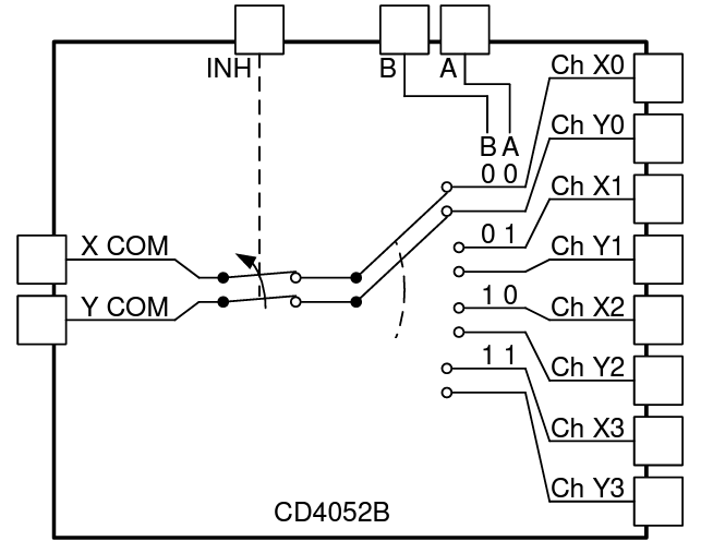
The CD4052B is a dual 2:4 Decoder/Multiplexer. Here’s the functional block diagram of the chip from Texas Instruments.
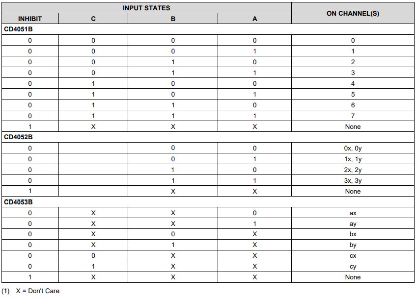
And here’s the lookup table to select the channels:
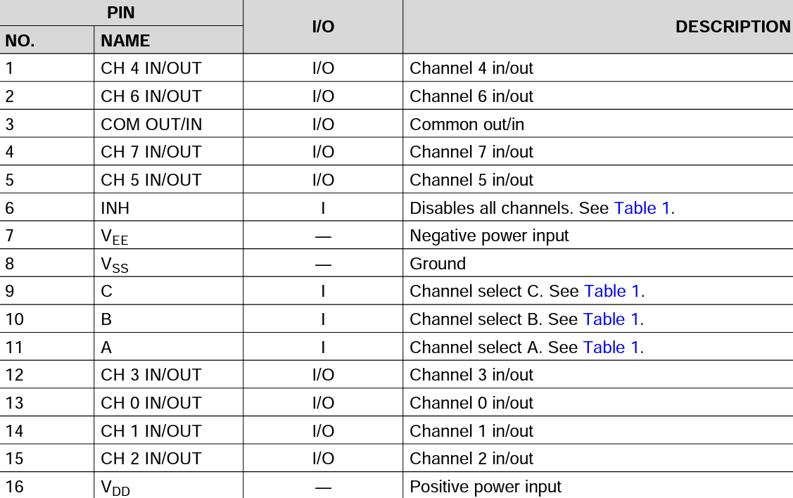
Last thing before we head to the code, here’s the CD4052B chip pin designations:
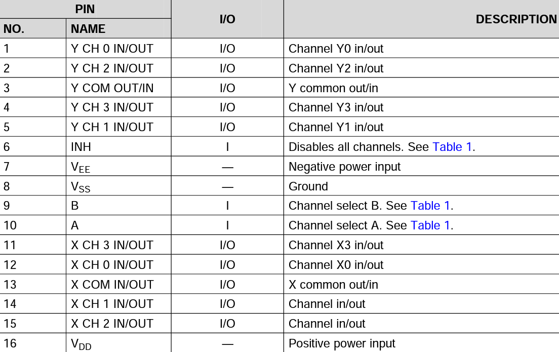
Head back to the truth table in our CD4051B discussion to see the referenced Table 1 above.
Now that you’re familiar with how the CD4052B chip works let’s walk through the code to understand how we'll simulate it on Wokwi.
This chip requires the same four files used in CD4051B with some variations. We’ll go through the Arduino Sketch, cd4052.chip.json, and cd4052.chip.c files. The diagram.json file will no longer be discussed as its purpose in this project is the same as that in CD4051B.
Arduino Sketch
Let’s discuss each block of code inside the sketch.ino file from top to bottom.
Define two constants to point A1, A0.
const int X_PIN_VALUE = A1;
const int Y_PIN_VALUE = A0;
The A1 and A0 are the analog input channels on the Arduino UNO. We will read the two analog inputs and print them on the terminal.
Declare the connection of Arduidno’s pins based on the pin designation from the table above.
const int PIN_INH = 7;
const int PIN_A = 4;
const int PIN_B = 5;
The pins A and B of the CD4052B chip are tied to Arduino pins 4 and 5, and the inhibit pin is connected to Arduino UNO’s pin 7.
const int SW_INH = 8;
const int SW_A = 9;
const int SW_B = 10;
We’ll control the values of A, B, and INH pins of the CD4052B using a DIP switch connected to Arduino Pins 9, 10, and 8, respectively.
Define the Arduino pins used in our project as inputs and outputs.
void setup() {
  Serial.begin(115200);
  Serial.println("Starting Demo");
  pinMode(X_PIN_VALUE, INPUT);
  pinMode(Y_PIN_VALUE, INPUT);
  pinMode(PIN_INH, OUTPUT);
  pinMode(PIN_A, OUTPUT);
  pinMode(PIN_B, OUTPUT);
  pinMode(SW_INH, INPUT_PULLUP);
  pinMode(SW_A, INPUT_PULLUP);
  pinMode(SW_B, INPUT_PULLUP);
  setRegisters(
    digitalRead(SW_INH),
    digitalRead(SW_A),
    digitalRead(SW_B)
  );
}
Add the loop() function.
void loop() {
  uint8_t inh = digitalRead(SW_INH);
  uint8_t a = digitalRead(SW_A);
  uint8_t b = digitalRead(SW_B);
  setRegisters(inh, a, b);
  Serial.print("X Value");
  Serial.println(analogRead(X_PIN_VALUE));
  Serial.print("Y Value");
  Serial.println(analogRead(Y_PIN_VALUE));
  Serial.println("------");
  byte result = 0b00000000;
  bitWrite(result, 3, inh);
  bitWrite(result, 2, a);
  bitWrite(result, 1, b);
  delay(1000);
}
We use this block of code to:
- Continuously apply the values read from the DIP switch to the CD4052B input pins;
- Read the analog pins
A1andA0; and - Display the analog values read on the terminal.
cd4052b.chip.json
Same as the cd4051b.chip.json file above, this file contains the name, author, and pins used in the project.
{
"name": "CD4052B",
"author": "Chris Schmidt",
"pins": [
     "Y-CIO0",
     "Y-CIO2",
     "Y-COMIO",
     "Y-CIO3",
     "Y-CIO1",
     "INH",
     "VEE",
     "VSS",
     "B",
     "A",
     "X-CIO3",
     "X-CIO0",
     "X-COMIO",
     "X-CIO1",
     "X-CIO2",
     "VDD"
   ]
}
The chip name is now updated to CD4052B. The pins are also updated in the same order they appear in the CD4052B’s datasheet.
cd4052b.chip.c
In this file, we’ll implement the function of the chip CD4052B. We’ll create a few “watches” so the chip will react to the changes in the inputs.
Let’s begin.
Include the same dependencies used in CD4051B.
#include "wokwi-api.h"
#include <stdio.h>
#include <stdlib.h>
Define the structure chip_state_t to hold all the variables or information you want it to pass along to the functions.
typedef struct {
  pin_t pin_xcomio;
  pin_t pin_ycomio;
  uint32_t xcio0_val;
  uint32_t xcio1_val;
  uint32_t xcio2_val;
  uint32_t xcio3_val;
  uint32_t ycio0_val;
  uint32_t ycio1_val;
  uint32_t ycio2_val;
  uint32_t ycio3_val;
  uint8_t inh;
  uint8_t a;
  uint8_t b;
} chip_state_t;
Map the input values A, B, and INH to three bits of a byte. It helps in understanding the implementation and comparing it with the lookup table in the datasheet, which is usually in binary.
static void bitWrite(uint8_t *x, char n, uint8_t value) {
  if (value)
    *x |= (1 << n);
  else
    *x &= ~(1 << n);
}
Add the update_output() function.
static void update_output(chip_state_t *chip) {
  uint8_t result = 0b00000000;
  bitWrite(&result, 0, pin_read(chip->b));
  bitWrite(&result, 1, pin_read(chip->a));
  bitWrite(&result, 2, pin_read(chip->inh));
  if (result == 0b00000000) {
    pin_dac_write(chip->pin_xcomio, pin_adc_read(chip->xcio0_val));
    pin_dac_write(chip->pin_ycomio, pin_adc_read(chip->ycio0_val));
  } else if (result == 0b00000001) {
    pin_dac_write(chip->pin_xcomio, pin_adc_read(chip->xcio1_val));
    pin_dac_write(chip->pin_ycomio, pin_adc_read(chip->ycio1_val));
  } else if (result == 0b00000010) {
    pin_dac_write(chip->pin_xcomio, pin_adc_read(chip->xcio2_val));
    pin_dac_write(chip->pin_ycomio, pin_adc_read(chip->ycio2_val));
  } else if (result == 0b00000011) {
    pin_dac_write(chip->pin_xcomio, pin_adc_read(chip->xcio3_val));
    pin_dac_write(chip->pin_ycomio, pin_adc_read(chip->ycio3_val));
  } else {
    // Latch mode, don't make any changes
    // TODO: This should maybe return "undefined" or something else?
  }
}
This function performs the following:
- Read three input pins (
B,A,INH) of the CD4052B chip; and - Based on the value of
AandB, update the two output pins of CD4052B using the analog values read from the corresponding channel input pins. - Assign the user set values using the DIP switch to the IC pins.
void chip_pin_change(void *user_data, pin_t pin, uint32_t value) {
  chip_state_t *chip = (chip_state_t*)user_data;
  update_output(chip);
  // Uncomment to DEBUG
  printf("Output X Value: %f\n", pin_adc_read(chip->pin_xcomio));
  printf("Output Y Value: %f\n", pin_adc_read(chip->pin_ycomio));
  printf("****Inside Chip Pin Change****\n");
}
Add the chip_init() function.
chip->pin_xcomio = pin_init("X-COMIO", ANALOG);
chip->xcio0_val = pin_init("X-CIO0", ANALOG);
chip->xcio1_val = pin_init("X-CIO1", ANALOG);
chip->xcio2_val = pin_init("X-CIO2", ANALOG);
chip->xcio3_val = pin_init("X-CIO3", ANALOG);
chip->pin_ycomio = pin_init("Y-COMIO", ANALOG);
chip->ycio0_val = pin_init("Y-CIO0", ANALOG);
chip->ycio1_val = pin_init("Y-CIO1", ANALOG);
chip->ycio2_val = pin_init("Y-CIO2", ANALOG);
chip->ycio3_val = pin_init("Y-CIO3", ANALOG);
The above lines of code initiates the chip’s 10 pins configured as analog pins. For more information on the APIs used to initialize the pins, please refer to APIs.
chip->inh = pin_init("INH", INPUT);
chip->a = pin_init("A", INPUT);
chip->b = pin_init("B", INPUT);
const pin_watch_config_t watch_config = {
  .edge = BOTH,
  .pin_change = chip_pin_change,
  .user_data = chip
};
pin_watch(chip->inh, &watch_config);
pin_watch(chip->a, &watch_config);
pin_watch(chip->b, &watch_config);We create three watch functions. The watch functions continuously watch the pin status and detect if there are any level changes on the pins.
If the level change type matches,
.edge = BOTH,the chip_pin_change() call back function will be called. In our example, we have set as BOTH the rising edge and the following edge, so whenever there is a change on the pins INH, A, and B, the callback function will be called.
const timer_config_t config =
{
  .callback = chip_timer_callback,
  .user_data = chip,
};
timer_t timer_id = timer_init(&config);
timer_start(timer_id, 1000, true);
update_output(chip);
}
The chip_timer_callback() updates the output pin status periodically. The period is defined in the config function. In this example, we have configured the timer to call the callback function every 1000 µs or 1 ms.
Final Results
Here’s the whole project so you can see the project’s functionality for yourself: CD4052B on Wokwi.
Conclusions
In this article, we learned how an existing custom chip CD4051B was built. Then, we applied the same concepts from that project to create our own CD4025B custom chip. We not only learned how to build the chip, we also came across several useful APIs.
We look forward to your suggestions and feedback. You can always say “hi” 👋 and meet fellow Wokwi users on Facebook, Discord, and Twitter.